Signal Integrity Considerations in Industrial Cable Assemblies
Industrial cable assemblies are becoming increasingly important as machines adopt higher-speed communication, distributed control, machine vision, advanced sensors, and connected automation systems.
A cable assembly may appear to be a simple combination of wires, connectors, and protective materials. However, when transmitting high-speed or sensitive signals, every part of the assembly can influence electrical performance.
Changes in impedance, geometry, shielding, routing, connector design, termination, and manufacturing consistency can affect signal quality.
For this reason, signal integrity should be considered from the cable and connector level through to the complete industrial system.
Why Signal Integrity Matters in Industrial Applications
Signal integrity refers to the ability of a cable assembly to transmit an electrical signal with sufficient quality and consistency from the source to the receiver.
Poor signal integrity can cause:
- Signal attenuation
- Reflections
- Crosstalk
- Electromagnetic interference
- Timing errors
- Increased bit-error rates
- Communication instability
- Intermittent equipment faults
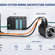
These problems can become particularly challenging in industrial environments because cables may operate alongside motors, drives, power supplies, relays, and other sources of electrical noise.
A communication system may therefore work correctly during initial testing but experience intermittent errors after installation in the actual machine.
This is why cable assembly design needs to consider both electrical performance and the real operating environment.
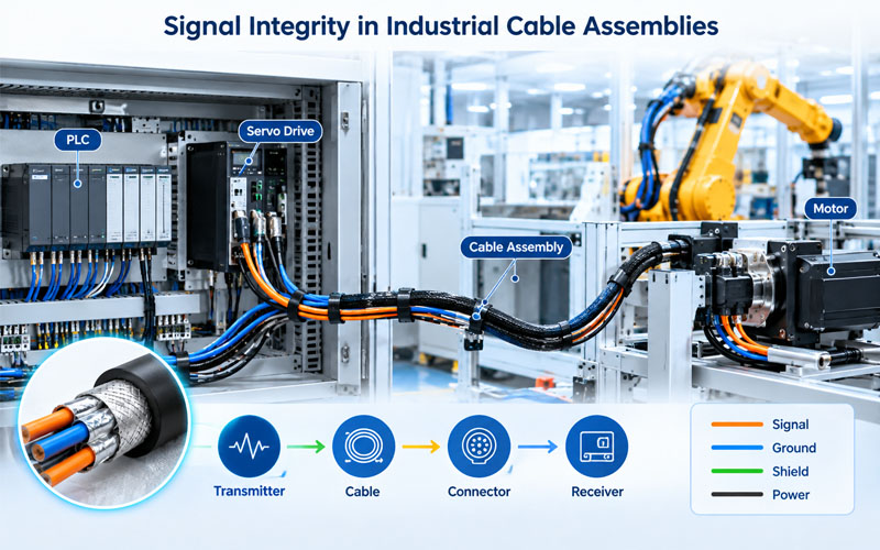
1.Understand the Signal Before Designing the Cable Assembly
The first step is to understand what the cable assembly needs to transmit.
Important parameters include:
- Signal type
- Frequency or data rate
- Differential or single-ended signaling
- Voltage level
- Required bandwidth
- Cable length
- Operating temperature
- Environmental conditions
- Required EMC performance
- Connector interface
A low-speed sensor cable and a high-speed industrial communication cable should not be designed using the same assumptions.
As signal speed increases, characteristics that may have been negligible at low frequencies can become important.
For example, the electrical behavior of the cable and connector becomes increasingly dependent on the physical geometry of the transmission path.
2.Impedance Control Is a Fundamental Consideration
For many high-speed and differential applications, controlled impedance is essential.
The characteristic impedance of a cable depends on factors such as:
- Conductor geometry
- Conductor spacing
- Insulation material
- Dielectric properties
- Shield structure
- Pair construction
If the impedance changes significantly along the signal path, part of the signal can be reflected toward the source.
This can distort the waveform received by the equipment.
A simplified signal path can be viewed as:
Transmitter → Cable → Connector → Cable → Receiver
Every transition along this path can potentially introduce an impedance discontinuity.
Therefore, impedance should be considered across the complete cable assembly, rather than only the cable itself.
3.Differential Pair Geometry Matters
Many industrial communication systems use differential signaling because it can provide good noise rejection when properly implemented.
The two conductors in a differential pair should maintain a controlled physical relationship.
Important factors include:
- Pair spacing
- Conductor diameter
- Twist rate
- Insulation thickness
- Pair-to-pair spacing
- Shield structure
If the geometry changes significantly during cable assembly, electrical characteristics may also change.
For example, excessive deformation near a connector termination can affect pair geometry and potentially degrade high-speed performance.
This makes controlled preparation and termination processes important for production consistency.
4.Cable Length Affects Signal Performance
Cable length should always be considered during signal integrity analysis.
Longer cables can introduce greater:
- Insertion loss
- Attenuation
- Propagation delay
- Exposure to external interference
- Opportunities for impedance discontinuities
The impact depends on the signal frequency, cable construction, conductor materials, dielectric characteristics, and communication protocol.
A cable assembly that performs well at a short length may not deliver the same performance when extended significantly.
For industrial equipment, the cable length should therefore be defined early in the design process.
5.Shielding Helps Protect Signal Quality
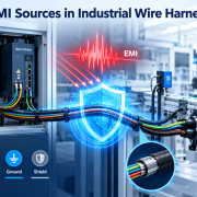
Shielding can reduce the impact of external electromagnetic interference and help contain unwanted emissions.
Common shielding structures include:
- Aluminum foil
- Copper braid
- Spiral shield
- Foil plus braid
- Shielded twisted pairs
The appropriate construction depends on the application.
However, shielding effectiveness is not determined by the cable alone.
The complete shielding path includes:
Cable Shield → Connector → Shield Termination → Equipment Interface
A gap or weak termination point can reduce overall protection.
This is particularly important for industrial automation systems where sensitive communication cables may operate close to motors and switching equipment.
6.Shield Termination Can Affect High-Speed Performance
The transition from the cable shield to the connector is an important part of signal integrity and EMC design.
Poor shield termination can create:
- Increased electromagnetic coupling
- Shield discontinuity
- Unwanted common-mode currents
- Increased susceptibility to external noise
For demanding applications, the termination should maintain the intended shielding structure as continuously as practical.
A 360° termination approach may be appropriate for some industrial applications because it maintains a more continuous conductive connection between the cable shield and connector interface.
The exact design should still be determined by the cable, connector, frequency range, mechanical requirements, and system grounding architecture.
7.Crosstalk Between Adjacent Signals
Crosstalk occurs when energy from one signal path couples into another.
It can become a concern when multiple signal pairs or circuits are placed closely together.
Potential causes include:
- Insufficient pair-to-pair spacing
- Long parallel routing
- Poor cable geometry
- Inadequate shielding
- Improper termination
A well-designed industrial cable assembly should therefore consider the relationship between adjacent circuits.
For example, sensitive communication pairs should not automatically be bundled directly alongside high-noise switching circuits simply because they fit within the same cable jacket.
8.Routing Is Part of Signal Integrity Design
Signal integrity does not end when the cable leaves the assembly.
Installation routing can significantly influence actual system performance.
Important routing considerations include:
Separate Sensitive and Noisy Circuits
Where practical, maintain separation between:
- High-speed communication cables
- Sensor wiring
- Encoder cables
- Servo motor cables
- High-current power cables
Avoid Unnecessary Parallel Runs
Long parallel runs between noisy and sensitive circuits can increase coupling.
Control Cable Bending
Excessive bending can alter internal cable geometry, particularly in high-performance differential cables.
Avoid Excessive Compression
Cable ties, clamps, or mounting structures should not deform the cable excessively.
The installation environment should therefore be considered during cable assembly design.
9.Connector Design Is Part of the Signal Path
A common mistake is to focus heavily on cable selection while treating the connector as a separate mechanical component.
For high-speed applications, the connector is part of the electrical transmission path.
Potential issues include:
- Contact geometry
- Pin arrangement
- Pair spacing
- Shield continuity
- Contact resistance
- Impedance transition
- Termination geometry
A connector with excellent mechanical performance may not automatically provide the required high-speed electrical performance.
The cable and connector should therefore be evaluated as a complete interconnect system.
10.Termination Quality Affects Consistency
Cable preparation and termination can directly influence signal performance.
Important manufacturing controls may include:
- Strip length
- Conductor exposure
- Pair geometry
- Shield preparation
- Contact crimping
- Soldering where applicable
- Connector insertion
- Strain relief
- Shield termination
For high-speed differential cables, maintaining consistent pair geometry during termination is particularly important.
Small differences between assemblies can create variation in electrical performance.
This is why process control becomes increasingly important as signal speed and performance requirements increase.
11.Mechanical Stress Can Become an Electrical Problem
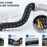
Industrial cable assemblies often operate under vibration, bending, torsion, and temperature cycling.
Mechanical movement can affect electrical performance over time.
Repeated movement may cause:
- Shield damage
- Conductor fatigue
- Geometry changes
- Contact movement
- Termination degradation
For dynamic applications such as robotics and automated equipment, cable construction and mechanical routing should therefore be designed together with signal integrity requirements.
A cable assembly should maintain its electrical characteristics throughout its expected service life—not only when it is new.
12.Temperature Can Change Electrical Characteristics
Industrial cable assemblies may experience substantial temperature variation.
Temperature can influence:
- Conductor resistance
- Insulation properties
- Dielectric characteristics
- Material dimensions
- Connector contact performance
For applications with demanding signal integrity requirements, these changes should be considered during design and validation.
A cable assembly intended for a controlled indoor environment may require a different design approach from one installed near a motor, inverter, outdoor machine, or high-temperature process.
13.Signal Integrity Testing
Visual inspection and basic continuity testing are important, but they may not reveal signal integrity problems.
Depending on the application, validation can include:
Electrical Testing
- Continuity
- Resistance
- Insulation resistance
- Shield continuity
- HiPot where applicable
Signal Integrity Testing
Depending on the interface and performance requirements:
- Insertion loss
- Return loss
- Impedance
- Crosstalk
- Propagation delay
- Eye diagram analysis
- Bit-error-rate testing
EMC Testing
Where required:
- Radiated emissions
- Conducted emissions
- Radiated immunity
- Conducted immunity
The appropriate test method should be selected according to the actual communication technology and system requirements.
14.Design for Manufacturing Matters
A cable assembly can perform well in a prototype but become inconsistent during mass production if the manufacturing process does not adequately control critical dimensions.
For signal-sensitive assemblies, production controls should focus on parameters such as:
- Cable preparation
- Strip dimensions
- Pair geometry
- Crimp height
- Terminal positioning
- Shield termination
- Connector assembly
- Pull-force requirements
- Final electrical testing
The goal is not simply to manufacture one good sample.
The goal is to achieve repeatable electrical performance across production batches.
This is especially important when industrial customers require long-term supply consistency.
15.A Practical Signal Integrity Design Workflow
A structured development process can reduce signal integrity risks early.
Step 1: Define the Interface
Identify the communication protocol, data rate, bandwidth, voltage, and required cable length.
Step 2: Select the Cable Construction
Evaluate conductor size, insulation, pair geometry, shielding, flexibility, and environmental requirements.
Step 3: Match the Connector
Verify contact arrangement, mechanical interface, shielding, and electrical characteristics.
Step 4: Control the Transmission Path
Maintain appropriate geometry through the cable, termination, connector, and equipment interface.
Step 5: Design the Routing
Consider separation, bend radius, mechanical protection, and proximity to noise sources.
Step 6: Control Manufacturing
Identify critical process parameters that can affect electrical performance.
Step 7: Validate the Complete Assembly
Test the finished cable assembly under representative electrical, mechanical, environmental, and EMC conditions.
This approach helps move signal integrity from a troubleshooting activity to an early-stage design requirement.
How FPIC Supports Customized Industrial Cable Assemblies
Industrial cable assemblies often require a balance between electrical performance, mechanical durability, connector compatibility, environmental protection, and manufacturing consistency.
FPIC supports customized cable assembly development for industrial applications, with solutions that can be adapted to application-specific cable, connector, shielding, termination, and testing requirements.
For signal-sensitive applications, the focus should be on the complete interconnect—from the transmitting device through the cable assembly to the receiving equipment.
Final Thoughts
Signal integrity is a system-level consideration that begins at the cable assembly.
Cable geometry, impedance, shielding, connectors, termination, routing, mechanical stress, and manufacturing consistency can all influence how reliably a signal reaches its destination.
As industrial equipment moves toward faster communication and more compact system architectures, cable assemblies need to be treated as engineered electrical components rather than simple wiring.
Designing signal integrity into the cable assembly from the beginning can help reduce communication errors, improve system stability, and minimize costly troubleshooting during production and field operation.
FAQ
What is signal integrity in an industrial cable assembly?
Signal integrity is the ability of a cable assembly to transmit a signal with sufficient quality and consistency from the source to the receiver without unacceptable distortion, loss, reflections, or interference.
Why is impedance important in high-speed cable assemblies?
Impedance discontinuities can cause signal reflections and waveform distortion. Maintaining controlled impedance helps preserve signal quality across the transmission path.
Does shielding improve signal integrity?
Shielding can reduce electromagnetic interference and help protect sensitive signals. However, shielding must be combined with appropriate termination, grounding, routing, and cable construction.
Can cable length affect signal integrity?
Yes. Longer cables can increase attenuation, propagation delay, and exposure to interference. The acceptable length depends on the signal characteristics and cable design.
Are connectors important for signal integrity?
Yes. Connectors form part of the transmission path. Contact geometry, pair arrangement, impedance transitions, shielding, and termination can all influence high-speed performance.
Is continuity testing enough for a high-speed cable assembly?
No. Continuity testing verifies basic electrical connections but does not fully evaluate signal integrity. Depending on the application, impedance, insertion loss, return loss, crosstalk, or other performance tests may be required.
Need a Custom Industrial Cable Assembly for Signal-Sensitive Applications?
FPIC provides customized cable and wire harness solutions for industrial automation, communication, machine vision, robotics, and other demanding applications.
Contact FPIC to discuss your cable construction, connector, shielding, termination, and testing requirements.
Resources
- IPC/WHMA-A-620 – Requirements and Acceptance for Cable and Wire Harness Assemblies: Industry reference for cable and wire harness assembly requirements, workmanship, materials, methods, and acceptance criteria.
- TE Connectivity – Electromagnetic Compatibility: Provides background on electromagnetic compatibility, interference control, and shielding considerations.
- TE Connectivity – EMI Shielding FAQs: Covers cable shielding, grounding, shielding effectiveness, and application considerations.
- Molex – Machine Vision System Design: Provides industrial machine vision interconnect considerations relevant to signal integrity, cable performance, and EMI control.