Twisted Pair Wire Harness: Why Twist Pitch Matters
A twisted pair wire harness can use the correct conductors, connectors and pinout yet perform differently from another apparently identical assembly. The difference may be in the physical relationship between the two signal wires: their spacing, twist pitch, symmetry and the length separated at each termination. Those details influence how the pair couples to interference and behaves as a transmission path.
In machinery, drives, sensors and control cabinets, communication wiring often runs near switching equipment and power cables. A pair that looks acceptable on a bench may have less operating margin after installation.
The engineering task is to preserve the specified geometry from cable preparation through connector assembly. Twist pitch is one controlled characteristic within that system. It cannot compensate for an unsuitable cable, incorrect pairing, poor termination or an unverified interface.
What Is Twist Pitch?
Twist pitch, also called lay length, is the axial distance over which a conductor makes one complete revolution around the pair axis. It is measured along the pair, not along the curved path of the individual wire.
A shorter pitch means more turns per unit length. A longer pitch means fewer. Adjacent visible crossings are not necessarily a full revolution, so counting every crossover as one turn can produce an incorrect result.
For a defined inspection span:
Average pitch = axial length of the span ÷ number of complete turns
The method needs a consistent viewing reference and measurement condition. Pulling a pair tight can change its geometry; measuring immediately under machine tension may give a different result from measuring after the assembly is released.
Keep three dimensions separate:
| Dimension | What it describes |
|---|---|
| Individual wire cut length | Material prepared before twisting and termination |
| Finished twisted length | Axial length of the completed paired section |
| Untwisted end length | Portion where the conductors separate for termination, measured from defined references |
Because the conductors follow a helix, wire cut length and finished axial length are not interchangeable. The process must account for the intended twist and final end configuration.
An acceptable average also does not prove local uniformity. A short loose section and a tightly twisted section can average out while leaving different geometry along the assembly.
Why “Twisted Together” Is Not Enough
Differential signaling relies on the voltage difference between two conductors. When external interference couples similarly into both, it appears mainly as common-mode noise, which a suitable receiver can reject within its operating limits.
Twisting repeatedly exchanges the conductors’ positions relative to nearby noise sources. Together with close spacing and balanced construction, this helps reduce unequal coupling. It does not make the pair immune to every field, transient or grounding problem. TI’s cable-selection and RS-485 guidance explain why physical symmetry and balanced coupling matter. [1][2]
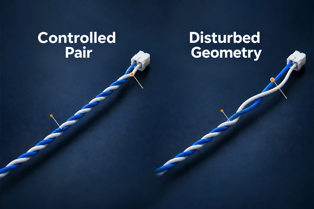
An assembly can lose that advantage when one wire spreads away from its partner, crosses another pair, or follows a different route into a connector. The pair may remain electrically continuous while becoming less balanced.
Several characteristics act together:
- conductor size and construction;
- insulation thickness and dielectric properties;
- conductor spacing and twist consistency;
- relationship to other pairs, shields and nearby metal;
- connector pin assignment and termination geometry.
Changing pitch can influence conductor path and electrical behavior, but impedance is not determined by pitch alone. A neat-looking pair made from arbitrary insulated wires is not automatically a compliant communication cable.
This is also why twisting and EMI shielding have different jobs. Pair geometry supports balanced transmission; shielding controls electromagnetic coupling through a separate structure and termination path. Neither replaces the other.
Is a Tighter Twist Always Better?
No. The objective is the approved construction, not the maximum number of turns the process can produce.
Tighter twisting changes the conductor path and mechanical condition. Excessive processing can create residual torsion, distort insulation or make subsequent handling difficult. A different lay may also affect the assembly’s electrical characteristics and finished length.
For factory-manufactured communication cable, preserve the supplied construction. Do not open and re-twist a qualified cable simply to make its appearance match another product. Different pairs within a multi-pair cable may intentionally use different lays to manage coupling.
For pairs formed during harness production, the drawing should define the wire combination, nominal pitch or permitted range, direction where relevant, finished length and open-end requirements. The resulting assembly still needs verification appropriate to its application.
TI’s termination guidance treats wire geometry, insulation and twist construction as contributors to the transmission line. It does not provide a single pitch that establishes compliance across interfaces. [3]
CAN, RS-485 and Industrial Ethernet Need Different Decisions
These technologies share an interest in balanced signal paths, but their physical-layer requirements are not interchangeable.
| Application | Important considerations | What must be confirmed |
|---|---|---|
| High-speed CAN / CAN FD | Pair balance, cable characteristics, topology, propagation and termination | Applicable CAN physical layer, data-phase requirements where used, cable specification and network design |
| RS-485-based communication | Cable and termination compatibility, edge rate, distance, loading and topology | Transceiver requirements and the actual system or fieldbus specification |
| Industrial Ethernet | Defined pair assignment, connector system, transmission bandwidth, loss, reflections and crosstalk | Ethernet physical layer, cable performance class and application-specific acceptance criteria |
RS-485 is an electrical interface standard, not a complete communication protocol or a universal cable specification. A system using it still needs an engineering decision about the medium and termination. [2]
For CAN FD, CiA’s cable guidance covers multiple electrical and mechanical properties, including twist rate, impedance tolerance, delay, loss and symmetry. Controlling twist alone cannot establish compliance with that scope. [4]
Industrial Ethernet also includes different cable constructions. PI’s PROFINET assembling guide describes a star-quad construction as well as multi-pair cable. Preserve the manufacturer’s defined geometry and pair assignments; do not assume every communication cable consists of interchangeable, independently twisted pairs. [5]
There is therefore no universal pitch or untwisted-length value for all three applications. Use the customer-approved cable specification, applicable physical-layer requirements and connector instructions.
Distinguish purchased cable from a pair formed during assembly
These are different manufacturing starting points. With purchased communication cable, the cable supplier controls its internal construction; the harness assembler must preserve that construction during preparation and termination. With two separately supplied wires, the assembler creates the pair geometry and needs an approved process for doing so.
A cable part number can therefore carry requirements that a wire-list note does not capture. Changing from a specified communication cable to shop-floor twisted singles requires engineering approval and appropriate validation. Matching wire gauge, color and apparent pitch is not enough to demonstrate equivalence.
Untwisted Length: Where a Good Pair Can Lose Its Geometry
The termination is often the most vulnerable transition. Conductors have to leave their paired arrangement and reach separate contacts, but unnecessary separation extends the region with different spacing and coupling.
Two assemblies can have the same central lay while differing substantially inside their connector backshells. One may maintain the pair close to the intended transition; the other may contain long separated tails routed around unrelated wires.
That difference can introduce imbalance, reflections or additional coupling. Its significance depends on the interface, signal edge characteristics, length and connector design—not only the nominal data rate.
Do not confuse strip length with untwisted length
Jacket removal exposes the cable’s internal structure. Conductor stripping removes insulation for a contact. Untwisting separates the paired conductors. These operations can overlap physically, but they require different controls.
A short conductor strip does not prove a short untwisted region. Likewise, an exposed pair can remain twisted after the outer jacket is removed.
Follow the connector’s intended transition
Define the measurement references: where controlled pair geometry ends and which contact or organizer feature establishes the endpoint. Show the arrangement before it becomes hidden.
Maintain the original pair as close to termination as the approved connector process requires. Do not force extra turns into a contact organizer, cross cavities or damage insulation just to minimize a visible dimension. Fluke Networks’ termination guidance emphasizes preserving geometry and following connecting-hardware instructions. [6]
For M12 cable assemblies, verify the actual coding, pair assignment, cable and termination system. The M12 mechanical interface alone does not establish suitability for a particular communication service.
How Programmable Twisting Improves Manufacturing Consistency
Manual twisting can produce acceptable assemblies when the process is defined and verified. Programmable automatic or semi-automatic equipment can reduce variation in repeated motion and setup.
The useful controls extend beyond rotation count:
- wire identity, diameter and prepared length;
- clamping position and grip condition;
- controlled tension or take-up behavior;
- rotation, direction and finished twisted length;
- open-end configuration;
- relaxation or compensation for springback, where supported;
- handling and end retention after release.
Komax’s bt 188 T is one public example of programmable semi-automatic twisting equipment, with optional end taping to limit untwisting. It illustrates an industry process approach, not an FPIC equipment declaration. [7]
Automation reproduces the selected setup. It does not prove that the selected setup is suitable for the signal.
The process must also accommodate the finished cable’s handling. Releasing clamps, transferring parts, inserting terminals and loading a harness board can disturb geometry. Verify the result after relevant operations rather than accepting the machine setting as the product measurement.
Where a wire, insulation or length changes, review the recipe. Similar nominal wire sizes can behave differently during twisting and relaxation.
How to Specify and Inspect a Twisted Pair Wire Harness
A useful drawing makes the critical geometry inspectable. “Twist these two wires” leaves too much open to interpretation.
| Characteristic | Information to define |
|---|---|
| Pair identity | Exact circuit members, wire specification and contact mapping |
| Pitch | Nominal or limits, full-turn convention and inspection region |
| Measurement state | Supported or released condition and permitted handling/tension |
| Finished length | Datums for paired section and overall assembly |
| Open ends | Untwisted-length references and permitted arrangement at each end |
| Retention | Approved tape, sleeve or other method, including location |
| Verification | Method, frequency, acceptance limits and required records |
Inspect representative regions, including areas near the transition to open ends. A long-span average can hide a local loss of twist.
First-article confirmation should check material identity, finished dimensions, local consistency, end geometry, insulation condition and correct connector loading. Where signal performance is critical, pair those geometric checks with the agreed electrical validation.
Examine the structure before potting, molding, sleeving or backshell closure hides it. A finished external photograph cannot establish the geometry inside the connector.
Repeat approval after relevant changes, such as a new wire construction, tooling adjustment, recipe revision or connector change. If variation is found, contain affected production, identify the last accepted condition, correct the process and verify new samples before release.
The aim is repeatable geometry tied to an approved specification, not simply a uniform-looking bundle.
A useful release record identifies the product revision, wire or cable lot, relevant process recipe, measurement references and results. Record the end configuration as well as the paired section. If an image is used, include a suitable scale and viewing direction; perspective can make pitch appear shorter or longer.
For a stable process, review the required sampling and change-point checks through the control plan. Neither a single approved prototype nor a machine’s repeatability claim determines the correct inspection frequency. Customer requirements and the consequences of a missed defect should guide that decision.
Why Continuity Cannot Prove Communication Performance
A basic electrical testing check can confirm that the expected conductive paths exist and that specified shorts or miswires are absent. It cannot, by itself, establish how the assembly transmits a communication waveform.
A split pair is a useful example. Conductors can connect to corresponding pins at both ends while the wrong physical wires form the signal pairs. A simple DC continuity check may pass, while a tester with appropriate split-pair detection identifies the problem. Fluke Networks documents this distinction. [8]
Signal edge rate also matters. A modest baud rate does not mean the waveform has only low-frequency content: fast rising and falling edges can expose transmission-line discontinuities. Consider propagation time relative to those transitions, as well as the data rate. During functional validation, use representative cable length, termination and operating conditions rather than relying only on a short, quiet bench setup.
Different verification methods answer different questions:
| Method | Main question |
|---|---|
| Continuity and circuit mapping | Are the specified conductive paths connected correctly? |
| Visual and dimensional inspection | Does accessible construction match the approved geometry? |
| Differential impedance / TDR, where specified | Are relevant impedance discontinuities present along the assembly? |
| Insertion and return loss | How much signal is lost, and how well are reflections controlled over the required band? |
| Crosstalk and balance measurements | Is unwanted coupling or mode conversion within the applicable limits? |
| Propagation delay and skew, where required | Does the transmission path meet the relevant timing requirements? |
| Functional or error testing | Does the selected system communicate under the defined conditions? |
Use limits appropriate to the actual interface and assembly. An Ethernet certification result is not a generic qualification for CAN or RS-485, and a CAN communication trial is not an Ethernet cabling test.
Fixtures and adapters matter. A test arrangement can add its own mismatch, loss or coupling, so define the measurement reference and suitable connection hardware. A successful bench exchange or link-up is useful evidence for that setup, but it does not automatically establish all required margins.
Fluke Networks distinguishes industrial Ethernet connectivity checks from broader cabling-performance verification. Specify which level the project requires and retain the corresponding results. [9]
Bringing Geometry Control into a Custom Industrial Project
FPIC supports industrial equipment wire harness projects through engineering review, wire processing, connector assembly, inspection and agreed testing.
Our manufacturing capability and quality assurance processes provide a basis for translating customer requirements into controlled production. For communication assemblies, the required twisting process and signal-verification scope should be confirmed during project evaluation.
Do not infer a specific high-frequency test capability from a general continuity or insulation tester. Agree on the test method, limits, responsible party and reporting before sample approval.
For an OEM/ODM cable assembly review, provide:
- cable or wire specification and drawing revision;
- communication interface, operating conditions and required performance;
- pair mapping, pitch limits and end-preparation requirements;
- connector part numbers, coding and assembly instructions;
- routing, shielding, motion and environmental conditions;
- required tests, sample quantities and production forecast.
Twist pitch is a manufacturing characteristic with electrical consequences. Control it together with pair geometry, connector transitions and verification of the finished signal path.
Send FPIC your drawing and communication requirements or email info@sz-fpi.com to discuss the application.
Frequently Asked Questions
1. What is the difference between twist pitch and twist rate?
Pitch is axial length per complete turn; twist rate is turns per unit length. A shorter pitch therefore means a higher twist rate. Use consistent units and the agreed measurement convention.
2. Can I use one pitch for CAN, RS-485 and Ethernet?
No universal value establishes suitability for all three. The correct construction depends on the cable, physical layer, connector, system design and customer specification.
3. Is the shortest possible untwisted end always correct?
No. Minimize unnecessary separation while following the connector’s approved preparation and routing instructions. Mechanical fit, insulation integrity and the intended contact transition still need to be preserved.
4. Can two ordinary wires become Ethernet cable by twisting them?
Twisting alone does not establish Ethernet compliance. The complete cable and connector system must meet the electrical, mechanical and transmission requirements of the selected application.
5. Does automatic twisting guarantee signal integrity?
No. It can improve process repeatability, but the recipe, materials, end preparation and subsequent handling still need control. Communication performance requires appropriate verification.
6. Why can a twisted cable pass continuity and still fail in service?
Continuity checks conductive paths at the time of test. Excessive untwisting, incorrect physical pairing, impedance discontinuities, loss or interference can impair communication while those paths remain connected.
Resources
- Texas Instruments — A Practical Guide to Cable Selection, SNLA164
- Texas Instruments — AN-1057, Ten Ways to Bulletproof RS-485 Interfaces
- Texas Instruments — RS-485 Basics: When Termination Is Necessary
- CAN in Automation — CiA 601 Series
- PI — PROFINET Assembling Guideline, Version 2.12
- Fluke Networks — Terminating a Category 6, 5e and 5 Connector
- Komax — bt 188 T
- Fluke Networks — Split Pair Identification
- Fluke Networks — Industrial Ethernet Testing