How to Control Crimp Quality in Large Cross-Section Power Harnesses
Large cross-section power harnesses are used in energy storage systems, industrial power equipment, battery cabinets, power distribution units, and other applications where high current must be transmitted reliably. In these assemblies, the crimped connection is a critical interface between the conductor and the terminal.
Unlike small-gauge signal wiring, large power cables often require heavier terminals, greater crimping forces, dedicated tooling, and more demanding conductor preparation. A connection may appear acceptable from the outside while still containing internal defects that affect contact resistance, mechanical strength, or long-term stability.
Effective crimp quality control therefore requires more than visual inspection or a single pull test. Manufacturers need a validated process that connects material selection, tooling setup, dimensional measurement, electrical verification, and production records.
1.Why Crimp Quality Matters in Large Power Cables
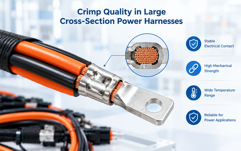
A crimped termination must provide both a mechanically secure connection and a stable electrical path. The crimping process compresses the conductor strands and terminal barrel into a controlled geometry that supports electrical contact and mechanical retention.
If the compression is insufficient, the joint may contain excessive voids or unstable contact interfaces. If compression is excessive, conductor strands may be damaged, the terminal barrel may deform improperly, or the connection may lose mechanical strength.
For high-current applications, even a small increase in connection resistance can become significant because resistive heating increases with the square of current.
[P=I^2R]
Where:
- (P) is the power dissipated as heat.
- (I) is the current flowing through the connection.
- (R) is the electrical resistance of the crimped interface.
For example, a resistance of just 100 micro-ohms produces 10 W of heat at 316 A, assuming that current and resistance remain constant. This is an illustrative calculation, not an acceptance limit for a specific terminal.
The practical implication is clear: crimp quality must be controlled as an electrical and mechanical performance requirement, not simply as an appearance criterion.
2.Match the Cable, Terminal, and Crimping Tooling
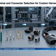
The first step is to establish compatibility among the conductor, terminal, and crimping equipment. A larger cable does not automatically require a particular crimp setting; the correct configuration depends on the complete termination design.
2.1 Verify conductor specifications
Before production, confirm the cable’s:
Nominal cross-sectional area and conductor material.
Stranded construction and strand arrangement.
Conductor class and applicable dimensional tolerances.
Insulation material, outside diameter, and stripping requirements.
Manufacturer’s specifications and applicable product requirements.
Copper and aluminum conductors should not be treated as interchangeable. Their mechanical behavior, surface characteristics, and termination requirements differ. Aluminum conductors, in particular, may require terminals and preparation methods specifically designed for aluminum.
For flexible fine-stranded cables, verify that the selected terminal and crimp profile are approved for the actual strand construction.
2.2 Confirm terminal compatibility
The terminal barrel must accommodate the conductor without excessive clearance or forced insertion. Check the approved cable cross-section range, barrel dimensions, material, plating, and crimp geometry.
For high-current power assemblies, terminal selection should also account for the intended current rating, temperature rise, environmental exposure, and mating interface.
Avoid mixing terminals and tooling simply because their nominal cable-size ratings appear similar. Different barrel designs can require different dies, crimp dimensions, and validation procedures.
2.3 Select appropriate crimping equipment
Large power terminals may require hydraulic crimpers, servo-controlled presses, or dedicated applicators, depending on the terminal design and production requirements.
Equipment selection should consider:
- Required crimping force and stroke.
- Die geometry and repeatability.
- Positioning and terminal alignment.
- Cable and terminal access.
- Cycle rate and production volume.
- Calibration, maintenance, and available monitoring functions.
The machine must be capable of producing the approved crimp geometry consistently throughout the production run. Rated force alone does not demonstrate that a machine is suitable for a particular terminal.
3.Control Conductor Preparation Before Crimping
Many crimp defects originate before the cable reaches the press. Inconsistent stripping, damaged strands, contamination, or incorrect insertion can undermine an otherwise validated crimping process.
3.1 Maintain consistent strip length
The stripped length must match the terminal design and work instructions. Too little exposed conductor may prevent the strands from reaching the required position inside the barrel. Excessive stripping may expose conductor beyond the intended crimp area or compromise insulation support.
Use controlled stripping equipment where appropriate, and verify strip length during setup and at defined intervals.
3.2 Prevent strand damage and material loss
Inspect stripped conductors for cut, nicked, missing, or excessively spread strands. Do not compensate for poor preparation by forcing the cable into the terminal.
For large conductors, handling and insertion can be more difficult because the cable is heavier and less flexible. Use suitable fixtures or positioning aids to prevent strand displacement and reduce operator variation.
3.3 Control conductor insertion depth
The conductor must be inserted to the position specified by the terminal design. Insufficient insertion can leave part of the intended crimp area without the required conductor material. Excessive insertion may interfere with terminal features or produce an unacceptable conductor projection.
Define a repeatable positioning method and make the relevant visual checks before crimping. Where the design requires a particular conductor brush or insulation gap, include it in the approved inspection criteria.
4.Establish a Validated Crimping Window
A reliable process uses documented, product-specific settings rather than adjustments based solely on operator judgment.
4.1 Define the critical process parameters
Depending on the terminal and equipment, controlled parameters may include:
- Crimp height or final crimp dimension.
- Crimping stroke and tool closure.
- Press force or force-displacement signature.
- Die and applicator identification.
- Cable and terminal specifications.
- Tool condition and maintenance status.
Not every parameter applies to every crimping system. The control plan should identify the variables that are technically relevant to the selected terminal.
4.2 Understand under-crimping and over-crimping
An under-crimped connection may have inadequate conductor compression, insufficient mechanical retention, or unstable electrical contact.
An over-crimped connection may experience excessive strand deformation, conductor damage, terminal cracking, or reduced pull-out strength.
The objective is not to maximize compression. It is to achieve the approved geometry and performance range for the specific conductor-terminal combination.
4.3 Validate settings before production
During initial setup, use representative production materials and the approved tooling configuration. Produce trial crimps, inspect their dimensions and appearance, and perform the required mechanical and electrical evaluations.
Only release the process after the results meet the applicable design specifications and acceptance requirements.
Repeat validation when a change could affect crimp performance, such as a new terminal supplier, conductor construction, tooling revision, or significant equipment change. The required extent of revalidation should be defined by the engineering change-control process.
5.Use Multiple Inspection Methods to Verify Crimp Quality
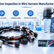
No single inspection method can detect every possible crimp defect. A robust inspection plan combines dimensional, mechanical, electrical, and, where necessary, destructive evaluation.
5.1 Crimp height measurement
Crimp height is a useful dimensional indicator when the terminal design defines a corresponding measurement method and acceptance range.
For large power terminals, measurement locations and instrument suitability are important. The tool must access the specified area, and the measurement procedure must be repeatable.
Record actual measurements rather than relying exclusively on a visual judgment that the crimp looks correct.
Crimp height should not be interpreted in isolation: identical measured dimensions do not guarantee identical internal conditions when conductor or terminal variation exists.
5.2 Pull force testing
Pull testing evaluates the mechanical retention of the conductor in the terminal. It can help identify inadequate compression, poor conductor insertion, or other process problems.
Acceptance criteria should come from the applicable terminal specification, customer requirements, or validated engineering documentation. Requirements vary with conductor size, terminal design, and application.
Pull testing is generally destructive to the tested termination. Establish a sampling plan that defines when tests are performed, how samples are selected, and what happens when a result fails.
A satisfactory pull force does not, by itself, prove that contact resistance or long-term thermal performance is acceptable.
5.3 Crimp cross-section analysis
Cross-section analysis exposes the internal structure of a crimp. It can help engineers evaluate strand distribution, conductor compression, voids, barrel deformation, and other features that cannot be reliably judged from the outside.
A typical process involves preparing a representative crimped sample, sectioning it at the specified location, polishing the surface, and examining the resulting profile.
Cross-section analysis is particularly useful during process development, tooling qualification, troubleshooting, and significant process changes.
Because it is destructive and requires suitable preparation, it is not a replacement for routine in-process controls. Its evaluation criteria must be defined for the actual terminal design; IPC/WHMA-A-620 does not itself establish criteria for cross-section or X-ray evaluation.
5.4 Electrical resistance and temperature-rise evaluation
Electrical testing verifies performance that mechanical inspection cannot fully establish.
Depending on the application, verification may include contact or connection resistance measurement, current-carrying capability, temperature-rise testing, and environmental or durability testing.
For high-current assemblies, resistance measurements require a suitable method, controlled test conditions, and appropriate instrumentation. Four-wire Kelvin measurement may be useful for low-resistance measurements because it reduces the influence of lead and contact resistance.
Temperature-rise testing should reflect the intended current, ambient conditions, cable configuration, terminal interface, and applicable product requirements.
Continuity testing alone is insufficient to demonstrate that a high-current connection has acceptably low resistance under operating conditions.
6.Common Crimp Defects and Their Controls
| Potential defect | Possible cause | Recommended control |
|---|---|---|
| Loose or insufficiently compressed crimp | Incorrect tooling, unsuitable settings, incompatible terminal | Verify tooling compatibility and approved crimp dimensions |
| Damaged or severed strands | Poor stripping, misalignment, excessive compression | Inspect conductor preparation and perform cross-section analysis where needed |
| Incomplete conductor insertion | Incorrect strip length, poor positioning, operator variation | Standardize insertion depth and add positioning checks |
| Uneven barrel deformation | Worn or misaligned dies, incorrect tool setup | Inspect tooling condition and verify alignment |
| Terminal cracking or severe deformation | Excessive compression, wrong die profile, unsuitable terminal | Stop production, investigate the cause, and revalidate the process |
| Excessive resistance or localized heating | Poor contact formation, contamination, damaged strands, unsuitable interface | Investigate resistance, material, crimp geometry, and thermal performance |
| Inconsistent results between production batches | Tool wear, material variation, uncontrolled changeovers | Trend process measurements and strengthen change control |
These are diagnostic starting points rather than one-to-one failure rules. A defect may have several contributing causes, so corrective action should be based on evidence from the actual process.
7.Build a Repeatable Production Control Plan
A validated setup is only the beginning. Consistent quality requires defined controls during routine production.
Step 1: Verify materials and tooling at setup
Confirm the cable specification, terminal part number, die or applicator, machine configuration, and revision-controlled work instructions before starting a batch.
Step 2: Inspect first-off samples
Evaluate the first production crimps against the approved visual and dimensional criteria. Complete any required mechanical or destructive checks before authorizing full production.
Step 3: Monitor critical process indicators
Use the measurements available for the selected process, such as crimp height, force signatures, or periodic pull test results. Establish inspection frequency according to risk, process capability, customer requirements, and historical performance.
Where force monitoring is used, define validated limits and alarm responses. A force signature is a process-monitoring signal, not automatic proof of a compliant crimp.
Step 4: Control tooling wear and maintenance
Heavy-duty crimping can place significant demands on dies, applicators, and presses. Inspect tools for wear, damage, contamination, and alignment issues according to a documented maintenance plan.
After tool replacement or adjustment, perform the required setup verification before resuming normal production.
Step 5: Define reaction plans for failures
When a measurement or test falls outside its approved limit:
- Stop or contain the affected production as required by the control plan.
- Identify potentially affected parts and batches.
- Check material, tooling, machine settings, and operator setup.
- Revalidate the process before releasing production.
- Document the root cause, corrective action, and verification results.
Do not simply adjust the press until one sample passes without understanding the cause of the deviation.
8.Connect Crimp Quality with Traceability
For power harnesses used in energy storage and industrial power distribution, traceability can help manufacturers investigate quality issues and demonstrate process control.
A useful production record may include:
- Cable and terminal part numbers and lot information.
- Crimping machine and tooling identification.
- Work order and production batch.
- Setup and inspection results.
- Pull test, cross-section, and electrical test records, where applicable.
- Operator or inspection authorization, as required.
- Nonconformance and corrective-action history.
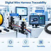
Digital production systems can link these records to the corresponding work order or product identifier. Barcode or QR-code scanning can also help reduce manual identification errors during material handling and production.
The goal is to make the connection between material, process, inspection result, and finished assembly clear enough to support timely investigation and continuous improvement.
9.Apply Risk-Based Validation to High-Current Applications
Not all large power harnesses have the same operating conditions. A cable used in a stationary battery cabinet may face a different combination of thermal, vibration, moisture, and maintenance requirements from one installed in mobile industrial equipment.
Engineering validation should therefore reflect the intended application.
Consider the following factors:
- Current and thermal load: Verify the complete connection under the specified operating conditions.
- Environmental exposure: Consider humidity, corrosion, temperature cycling, and other relevant stresses.
- Mechanical loading: Evaluate cable support, bending, vibration, and strain relief around the termination.
- Installation and serviceability: Ensure the cable can be routed, installed, and maintained without placing unintended loads on the crimp.
- Change sensitivity: Determine which material, tooling, and process changes require renewed qualification.
Crimp validation should be integrated with the broader cable assembly validation plan. A good termination cannot compensate for inadequate cable sizing, poor routing, unsuitable insulation, or an incorrectly specified terminal interface.
How FPIC Supports Power Harnesses Quality
For customized power harnesses, consistent quality begins with matching the conductor, terminal, and manufacturing process to the intended application.
FPIC provides customized wire harness and cable assembly solutions for industrial and energy-related applications. For projects involving large cross-section power cables, early alignment on cable specifications, terminal selection, current requirements, installation conditions, and inspection expectations helps establish a clearer manufacturing and validation plan.
Customers should define applicable acceptance criteria and required test evidence during the engineering stage, particularly for high-current or safety-critical assemblies.
Conclusion
Controlling crimp quality in large cross-section power harnesses requires a systematic approach. Material compatibility, conductor preparation, tooling selection, validated crimp dimensions, mechanical testing, electrical verification, and traceability must work together.
Crimp height and force monitoring can support process control, while pull testing and cross-section analysis provide additional evidence during qualification and production verification. Electrical resistance and temperature-rise evaluations address performance requirements that cannot be established by appearance alone.
The most reliable strategy is to define acceptance criteria before production, monitor the critical variables throughout manufacturing, and use documented evidence to investigate deviations and improve process consistency.
FAQ
What is the most important parameter for controlling large cable crimp quality?
There is no single universal parameter. Crimp height, tooling configuration, conductor preparation, and mechanical and electrical test results all provide different information. The applicable terminal specification and validated process should determine which parameters are critical.
Can crimp height alone confirm a good power cable connection?
No. Crimp height is a useful dimensional indicator, but it cannot independently establish internal strand condition, mechanical retention, or electrical performance. It should be used alongside other appropriate verification methods.
Why is cross-section analysis useful for large cross-section power harnesses?
It reveals internal crimp geometry and conductor deformation that may not be visible externally. It is particularly useful for initial qualification, process troubleshooting, and evaluating significant changes to materials or tooling.
Is pull force testing sufficient for high-current cable terminations?
No. Pull force testing evaluates mechanical retention, not the complete electrical performance of the connection. Depending on the application, resistance measurement and temperature-rise or other qualification tests may also be required.
How often should crimp quality be inspected during production?
The frequency should be established in the control plan based on product risk, process capability, customer requirements, and historical results. Setup verification, periodic dimensional checks, and defined mechanical or electrical test intervals may all be appropriate.
Which standard can be used for wire harness crimp workmanship?
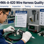
IPC/WHMA-A-620 provides requirements and acceptance criteria for cable and wire harness assembly workmanship, including crimped connections. The applicable revision, product class, customer requirements, and any additional application-specific criteria should be agreed upon for each project.
Planning a customized power wire harness?
Share your cable cross-section, current requirements, terminal specifications, operating environment, and testing expectations with FPIC. These details help establish an appropriate manufacturing and quality-control approach for your application.
Contact FPIC to discuss your custom wire harness requirements.
Resources
- TE Connectivity – Crimp Height: Employing an Effective Crimp Quality Metric
Explains the role of crimp height, tooling validation, and process consistency in achieving reliable crimped connections. - TE Connectivity – Crimp Quality Guidelines
Provides visual guidance on correct and incorrect crimp characteristics, conductor positioning, and tooling compatibility. - IPC – IPC/WHMA-A-620 Requirements and Acceptance for Cable and Wire Harness Assemblies
Official standards resource for cable and wire harness workmanship requirements and acceptance criteria. - Wiring Harness Manufacturer’s Association – Understanding the Foundations of IPC/WHMA-A-620
Discusses how workmanship standards support consistent manufacturing, inspection, and communication between customers and suppliers.