Why Wire Harness In-Process Inspection Matters
Wire harness in-process inspection verifies materials, wire preparation, crimps, connector assembly, routing, and electrical characteristics while the harness is being built—not only after every sleeve, branch, tie, label, and connector is complete. Its purpose is to detect a defect close to the operation that created it, contain the affected output, correct the process, and preserve evidence before the problem spreads through a production lot.
Final inspection remains necessary, but it is the last release gate rather than the first meaningful quality check. A completed harness may pass continuity while still containing a mechanically weak crimp, the wrong wire specification, an incorrect branch length, incomplete terminal locking, damaged insulation, or an identification error. Layered controls answer different questions at the stages where those questions can be evaluated most effectively.
For custom OEM cable assemblies, the practical quality sequence is:
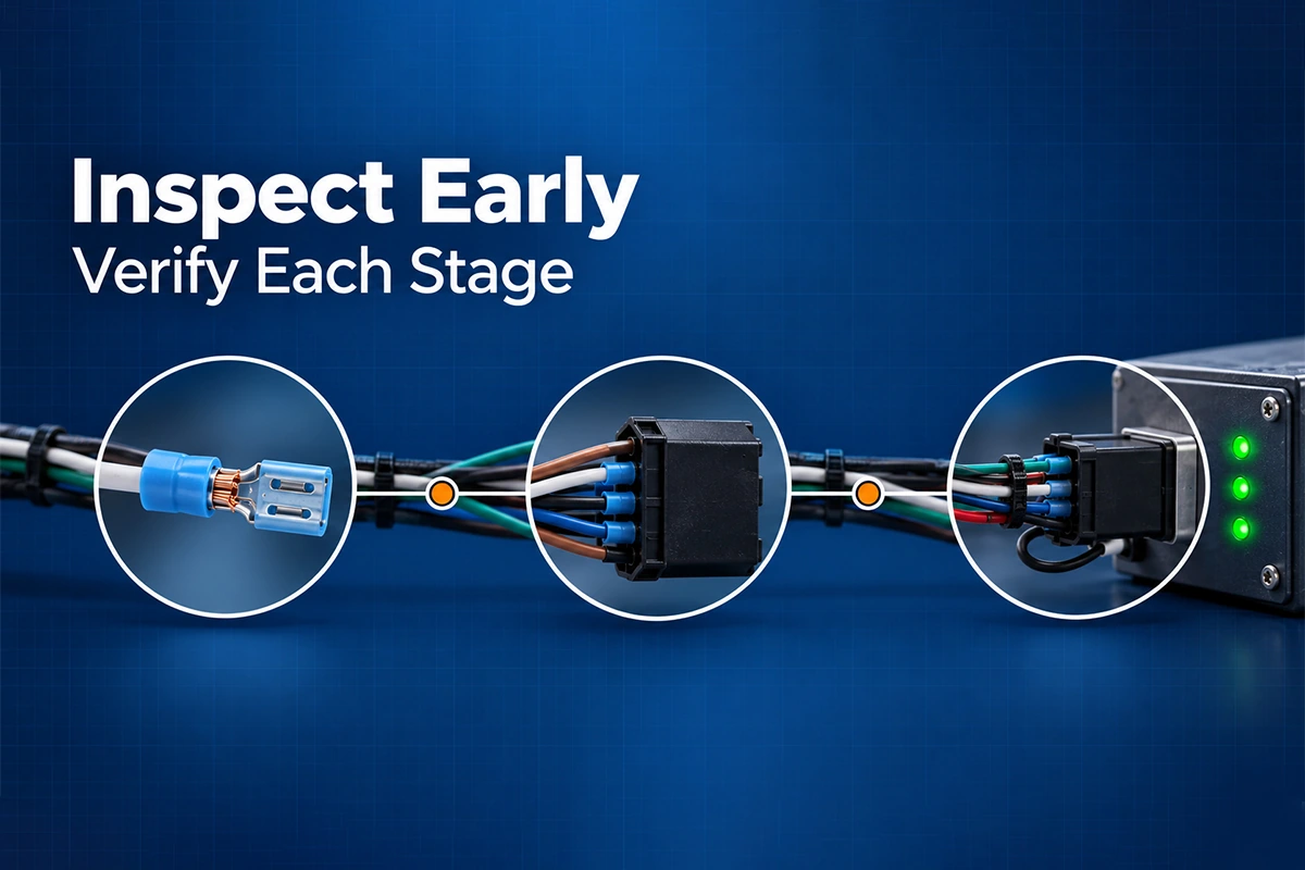
Incoming Material Verification → Crimp Process Control → In-Process Inspection → Connector and Pin Verification → Electrical Test → Final Inspection
What Does In-Process Inspection Mean in Harness Production?
In-process inspection is planned verification between incoming inspection and final release. It can include first-piece approval, operator checks, patrol inspection, sampled measurements, automated monitoring, and hold points before work becomes concealed or difficult to reverse.
The control plan identifies the characteristic, specification source, method, equipment, frequency, owner, record, and reaction to failure. Scope depends on the drawing, terminal requirements, product risk, process capability, customer agreement, and applicable standards—not a checklist copied across unrelated assemblies.
This approach separates three quality questions:
- Was the correct input used? Material and document verification address identity and revision.
- Was each critical operation performed correctly? Process controls evaluate cutting, stripping, crimping, insertion, routing, and other assembly steps.
- Does the completed product meet release requirements? Electrical, dimensional, visual, functional, documentation, and packaging checks support final acceptance.
Why a Final Continuity Pass Does Not Prove Crimp Reliability
A continuity test checks whether an electrical path exists between programmed points within the tester’s defined limits. Depending on the test method, it may also detect open circuits, short circuits, and miswires. This evidence is essential, but it does not establish every mechanical and metallurgical characteristic of a crimped connection.
A marginal termination may conduct during testing even when compression, strand condition, wire position, bellmouth, insulation support, or retention is unacceptable. Movement, vibration, handling, or thermal cycling can later expose the weakness. Conversely, a well-formed crimp cannot compensate for a wrong circuit or untested short.
Contact-resistance testing can detect some abnormalities that basic continuity may miss, but it does not measure pull strength, verify crimp geometry, identify all strand damage, or confirm terminal-to-housing retention. Insulation-resistance and dielectric-withstand tests address other specified risks.
The central rule is simple: a test result proves only the characteristics that the approved method, limits, fixture, and program were designed to evaluate. Electrical testing complements crimp and assembly controls; it does not replace them.
Why Late Discovery Makes Harness Rework Expensive
Defect cost rises as value is added. A wrong wire found after cutting may require replacing one lead. Found after terminals, housings, sleeves, labels, ties, seals, and coverings are installed, it may require diagnosis, disassembly, extraction, replacement, re-routing, reinspection, and retesting.
Late rework creates risks beyond labor:
- Extraction can damage terminal locks, seals, housings, plating, or conductors
- Removed terminals or single-use protection parts may not be reusable
- Rework can disturb correct circuits positioned beside the defect
- Finished dimensions and identification may need renewed verification
- The affected quantity is harder to determine when records do not show the failure point
- Production scheduling, shipment readiness, and customer approval may be disrupted
Rework should follow a controlled instruction and inspection route. Early detection allows the manufacturer to stop the operation, segregate suspect output, confirm the last accepted check, correct the cause, and authorize restart.
What Do Crimp Height, Pull Force, and Electrical Tests Detect?
These methods provide complementary evidence and should not be treated as interchangeable.
| Control method | Primary question | Typical value | Important limitation |
|---|---|---|---|
| Crimp-height measurement | Is the conductor barrel compressed to the specified geometry? | Non-destructive process measurement that can reveal setup or tooling drift | Does not by itself prove circuit position, terminal retention, or every internal crimp feature |
| Pull-force test | Does the crimped wire meet the specified mechanical retention requirement? | Destructive verification of termination strength under a defined method | Does not prove correct pinning or every electrical and visual requirement |
| Visual crimp inspection | Are wire position, conductor brush, bellmouth, insulation support, terminal shape, and visible damage acceptable? | Detects assembly features not represented by one numeric measurement | Cannot see every internal feature or quantify electrical performance |
| Continuity and wiring test | Are required points connected, and are programmed opens, shorts, or miswires absent? | Confirms circuit mapping against the approved test program | May pass a mechanically weak termination that still conducts during the test |
| Resistance, insulation, or withstand-voltage test | Do specified electrical characteristics meet defined limits? | Adds evidence for contact path or insulation integrity when required | Must use suitable fixtures, limits, safety controls, and an approved project-specific method |
IEC 60352-2:2024 addresses general requirements, test methods, and practical guidance for solderless crimped connections within its stated scope. Component-manufacturer specifications remain essential because the correct crimp height, wire range, strip length, tooling, and pull-force requirements are specific to the terminal system. Molex, for example, directs users to the applicable Application Tooling Specification for these values and emphasizes verification during tool use.
How Wire Harness In-Process Inspection Works
The most effective inspection plan follows the manufacturing sequence and places each check before the relevant feature becomes hidden, combined with other work, or costly to repair.
1. Incoming Material Verification
Confirm that wires, terminals, connectors, housings, seals, sleeves, labels, and other specified materials match the released BOM and approved manufacturer information. Checks may cover part identity, revision or status, supplier and lot documentation, quantity, appearance, dimensions, plating or compliance evidence, and storage condition where applicable.
Incoming verification does not require every laboratory test on every delivery. Its level should reflect supplier control, component risk, customer requirements, history, and the quality plan. The goal is to stop an incorrect input before it becomes many assemblies.
2. Wire Cutting and Stripping Checks
Verify wire type, size, color, cut length, strip length, insulation, conductor exposure, and strand condition. Excessive stripping can expose conductor outside the barrel; insufficient stripping can prevent correct placement; cut strands can reduce effective conductor area and strength.
The measurement method matters. Flexible wire length should be checked using defined datums and handling conditions so that operators and inspectors interpret the drawing consistently.
3. Crimp Setup and Process Control
Before production, match the terminal, wire, tool, press, locator, and released parameters. Setup verification may include crimp height, visual criteria, pull force, and cross-section analysis when required. Routine controls follow the approved frequency.
Crimp height is commonly non-destructive; pull testing is destructive and normally uses dedicated specimens. Automated monitoring can add cycle-level information, but alarms and thresholds still require validation and a reaction plan. TE Connectivity uses crimp-height analysis as a core method in its crimp-quality monitoring system.
If a result is outside the approved limit, do more than adjust the tool. Identify the last accepted result, isolate potentially affected output, evaluate tool wear, setup, wire and terminal identity, strip condition, measurement method, and equipment status, then document restart approval.
4. Connector, Pin, and Subassembly Verification
Check wire-to-cavity position, connector orientation, terminal seating, primary retention, secondary locks, seals, plugs, splices, shield terminations, and subassembly identification before covering or final bundling. A pin can be electrically correct yet incompletely locked, while a terminal can be fully seated in the wrong cavity.
For complex harnesses, staged comparison against the pin map and connector view reduces final diagnosis. Fixtures, barcode validation, vision, or poka-yoke can support the check, but each method must use the correct revision.
5. Routing, Protection, and Dimensional Inspection
Inspect branch lengths, breakouts, connector direction, labels, sleeves, clips, grommets, ties, bends, and protection before access becomes difficult. Use specified datums, tolerances, fixtures, and measurement conditions for critical dimensions.
This stage is also the right time to check whether protection covers the intended area without creating stress at the terminal or connector. Electrical testing cannot determine whether a branch reaches its mounting point or whether a clip faces the correct direction.
6. Electrical Testing Before Final Release
Run the approved program after circuit assembly and after rework or later operations that could affect it. The project may require continuity, wiring sequence, shorts, resistance, insulation, withstand voltage, shielding, or functional checks; not every harness requires every test.
Control the fixture, connector adapters, program identifier, revision, limits, and pass/fail record. A correct harness tested against an obsolete pin map can fail incorrectly; an incorrect harness tested against the same obsolete definition can be accepted. Test-program revision control is therefore part of product configuration control.
7. Final Inspection and Shipment Release
Final inspection confirms configuration and release status. It may cover appearance, dimensions, orientation, cleanliness, damage, quantity, packaging, documentation, test completion, deviations, and customer requirements.
It should verify that earlier controls were completed, not attempt to recreate every hidden process check. Once terminals, splices, or routing details are covered, final visual inspection may no longer have access to the evidence that was available during assembly.
Why High-Mix Harness Production Needs Stronger Process Discipline
High-mix manufacturing combines frequent changeovers with different wire gauges, colors, lengths, terminals, housings, pin maps, labels, fixtures, and test programs. Operators may build lower quantities of each variant, so repetition alone provides less protection against setup errors. Similar-looking components can also belong to different assemblies.
Risk rises at product changeover. The line must clear previous materials and documents, load the correct program, verify tooling, confirm the first piece, and preserve separation between variants. Inspection should respond to these risks rather than simply increase final sampling.
A useful high-mix strategy includes controlled kitting, barcode or part-number verification, revision-controlled visual instructions, first-piece release, defined hold points, connector-level checks, and electronic test-program selection where appropriate. The process should also specify what happens after tool change, material-lot change, maintenance, interruption, engineering change, or restart.
How Should an Inspection Control Plan Be Designed?
A control plan converts technical requirements and process risks into executable checks. For each characteristic, define:
- Requirement source: drawing, BOM, application specification, customer standard, or approved work instruction
- Manufacturing stage and the point at which the feature is still visible or correctable
- Inspection or monitoring method, equipment, and applicable calibration status
- First-piece, lot, shift, changeover, periodic, or other project-defined frequency
- Record type and traceability identifier
- Acceptance limit and decision authority
- Reaction plan for failure, including containment and restart
Avoid selecting a frequency only because it is convenient. A stable automated cut length, a destructive pull test, a manual pin insertion, and a safety-related electrical characteristic require different controls. Process capability, history, detection method, severity, and customer requirements should guide the decision.
IPC/WHMA-A-620F describes materials, methods, tests, and acceptance criteria for cable and wire harness assemblies. When specified, it supports a common workmanship framework, but it does not replace the drawing, terminal application data, product class agreement, or customer-specific control plan.
How Inspection Records Connect to Traceability
An isolated “PASS” result has limited diagnostic value. Useful records connect the result to the product configuration and manufacturing event. Depending on project requirements, the record chain may include:
- Harness part number, drawing or BOM revision, work order, lot, or serial number
- Material part numbers, suppliers, and relevant lots
- Machine, applicator, fixture, gauge, and test-program identifiers
- Operator or inspector, date, time, and production stage
- Actual measured values where required, not only pass/fail
- Nonconformance, containment, rework, retest, and release status
- Finished-product and shipment identification
This connection helps a manufacturer determine which units share a suspect material lot, tool setup, process window, or test program. It also helps demonstrate that the shipped product completed the required controls. Traceability scope should match risk and customer requirements; collecting disconnected data does not create a useful history.
FPIC’s article on custom wire harness traceability explains how material, process, inspection, electrical-test, and shipment information can form that production record chain.
How FPIC Applies Layered Wire Harness Quality Control
FPIC supports custom wire harness manufacturing through controlled material, production, inspection, testing, and record-management processes. FPIC’s documented quality-assurance process covers incoming material inspection, wire cutting and stripping, terminal crimping, housing insertion, assembly and routing, electrical testing, dimensional and visual inspection, final release, and outgoing inspection.
Relevant controls can include wire and strip length, conductor condition, crimp height, pull force, terminal position, insulation support, pin position, locking status, wiring sequence, connector orientation, branch length, labeling, and protection. Electrical capabilities can include continuity, wiring-sequence, contact-resistance, insulation-resistance, withstand-voltage, and functional verification according to product structure and customer requirements.
FPIC also uses ERP, MES, WMS, PLM, and related systems to support materials, engineering data, work instructions, production tracking, inspection records, and batch history. The exact inspection frequency, test scope, acceptance criteria, and retained records are defined for the project rather than applying every available method to every harness.
Customers can review FPIC’s manufacturing capabilities, testing and quality resources, and OEM/ODM support when evaluating a custom program.
What Should OEM Buyers Ask a Harness Supplier?
Before approving production, ask the supplier to explain:
- Which characteristics are verified at incoming, setup, in-process, electrical-test, and final stages
- How the terminal, wire, tooling, and crimp specification are matched
- When crimp height and pull force are checked and what triggers containment
- How pin maps and electrical-test programs are created, approved, and revision controlled
- Which features are inspected before sleeves, tapes, molding, or other coverings hide them
- How high-mix changeovers and first pieces are controlled
- How rework is authorized, performed, reinspected, and retested
- Which measured values and traceability records can be provided
- How an engineering or material change affects inspection and revalidation
The supplier’s answer should describe a connected process, not only show a final tester. Equipment is useful when the applicable method, limits, records, and reaction plan are also controlled.
Conclusion
Wire harness quality is built and verified throughout production. Incoming checks prevent the wrong input from entering the process; cut-and-strip inspection protects wire preparation; crimp controls evaluate termination quality; connector checks confirm insertion and locking; electrical tests verify the programmed circuit; and final inspection confirms release readiness.
No single test can replace this layered evidence. Detecting a problem near its source reduces rework exposure, improves containment, and creates more useful traceability for future investigation and repeat production.
If you are developing or transferring a custom cable assembly, send FPIC your project requirements. Include the drawing, BOM, pin map, application conditions, production volume, workmanship criteria, required tests, inspection records, and traceability expectations. FPIC can review the appropriate manufacturing and quality-control plan with your team.
Email: info@sz-fpi.com
Frequently Asked Questions
Is final electrical testing enough for a wire harness?
No. Electrical testing verifies only characteristics covered by its program, fixture, method, and limits. Material identity, length, locking, crimp geometry, retention, routing, protection, labels, and workmanship require other controls.
Can a weak crimp pass a continuity test?
Yes. A marginal crimp may conduct during a static test despite inadequate compression, damaged strands, poor wire position, or insufficient retention. Crimp inspection and process verification are also required.
What is the difference between crimp height and pull force?
Crimp height is normally a non-destructive measurement of conductor-barrel compression. Pull force is a destructive test of mechanical retention under a defined method. They evaluate different characteristics and must use limits from the applicable terminal, customer, or validated process specification.
When should pin verification occur?
Verify cavity position, wire sequence, terminal seating, locks, seals, and connector orientation before final covering or bundling makes correction difficult. Electrical testing should then confirm the approved circuit definition, but it may not detect incomplete mechanical locking.
Why is high-mix harness production more difficult to control?
Frequent product changeovers introduce different parts, tools, instructions, pin maps, and test programs. Controlled kitting, line clearance, first-piece approval, revision control, staged inspection, and program verification reduce the risk of mixing similar variants.
What records should be linked to a harness test result?
The required scope depends on the project, but useful records can link the result to the part and revision, work order or lot, material identity, equipment and tooling, test-program version, operator or inspector, measured values, rework status, and shipment record.
Resources
- IPC – IPC/WHMA-A-620F Standard
IPC identifies IPC/WHMA-A-620F as the cable and wire harness assembly standard covering materials, methods, tests, and acceptance criteria. - IEC – IEC 60352-2:2024 Solderless Crimped Connections
The official IEC publication provides general requirements, test methods, and practical guidance for solderless crimped connections within its stated scope. - Molex – Application Tooling and Crimp Verification Guidance
Molex’s official tooling page explains where product-specific crimp height, pull force, and strip-length requirements are controlled and why tooling must be verified during production. - TE Connectivity – Crimp Quality Monitoring
TE describes continuous crimp-height analysis as a non-destructive process-monitoring method and identifies data storage and traceability functions in its monitoring system. - FPIC – Wire Harness Quality Assurance and Testing
FPIC’s quality page documents incoming, in-process, final, and outgoing controls together with electrical, mechanical, dimensional, process-control, and traceability capabilities.