Why Conductor Nicking Matters in Wire Harness Reliability
Conductor nicking in wire harnesses is easy to underestimate because the defect may be small, hidden after crimping, and electrically continuous at the time of final test. Yet a blade mark on one or more strands can reduce mechanical margin exactly where the wire is already exposed to crimping, handling, vibration, and bending. A harness may pass a continuity check today and still develop an open circuit months later in the machine.
That is why stripping should not be treated as a simple preparation step. It is a controlled manufacturing process with direct consequences for connection strength and service life. The practical question is not only, “Was the insulation removed?” It is also, “Were the conductor strands left in the condition required by the drawing, workmanship standard, and validated process?”
This article looks at how nicks form, what they do to a stranded conductor, why some inspection methods miss them, and how first-article confirmation and ongoing monitoring can keep the process stable.
What Is a Conductor Nick?
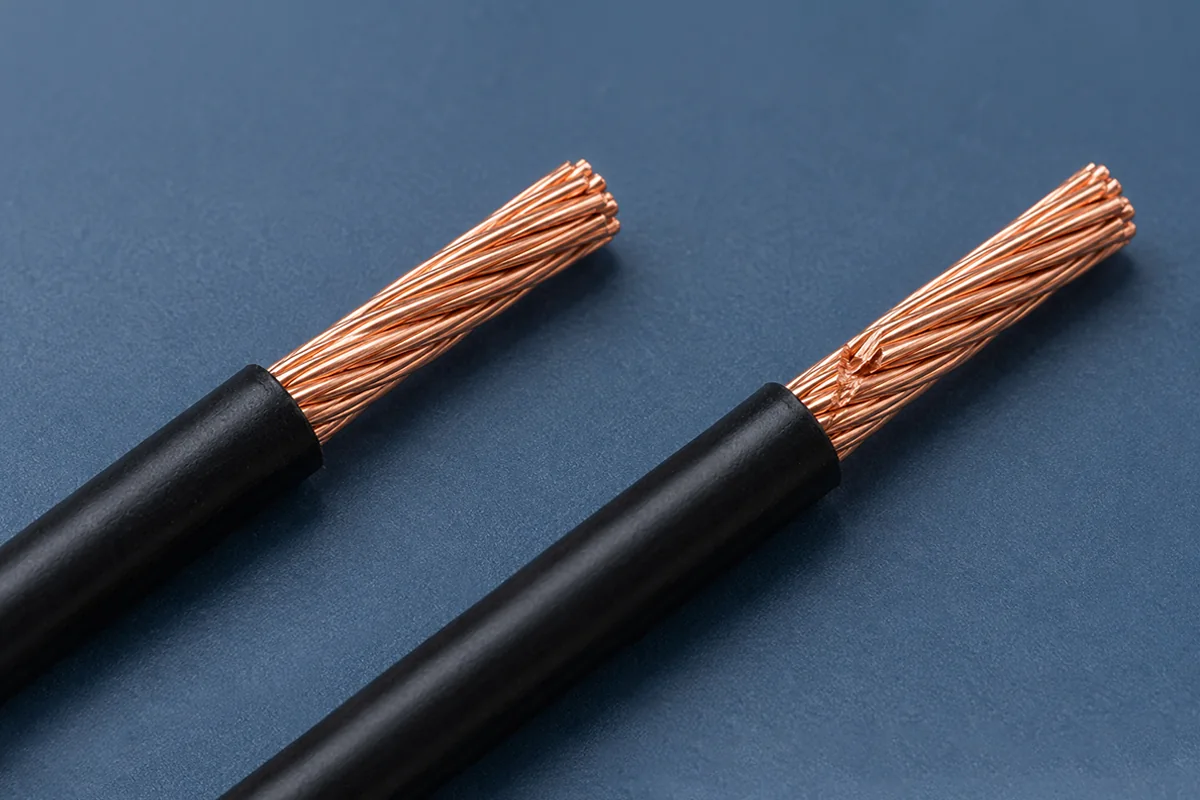
A conductor nick is a localized cut or indentation in a metallic strand, usually created while insulation is being removed. The damage can range from a light surface mark to a deep notch that removes part of the strand diameter. A strand may also be scraped, gouged, partially severed, or completely cut away.
These conditions should not be grouped together casually:
| Condition | What it looks like | Why the distinction matters |
|---|---|---|
| Surface witness mark | A visible mark with little or no measurable metal loss | It may still require evaluation against the applicable acceptance criteria. |
| Nick or notch | A localized cut into a strand | It reduces the strand’s local section and creates a stress concentration. |
| Scrape or gouge | Metal has been displaced or removed along a short length | The affected area may be larger than a single blade line. |
| Partially cut strand | A strand remains attached but has lost much of its section | It can break during crimping, pull testing, installation, or vibration. |
| Severed or missing strand | One or more strands are cut off | Both conductor area and mechanical contribution have been lost. |
| Insulation damage | The conductor may be intact, but insulation is cut, torn, or stretched | This creates a different electrical, sealing, or strain-transfer risk. |
The governing specification matters. NASA workmanship requirements, for example, reject conductors that are nicked, cut, or scraped to expose base metal in the covered applications. IPC/WHMA-A-620F provides industry acceptance requirements for cable and wire harness assemblies, but the correct class, drawing notes, customer requirements, and supplier instructions still need to be identified for each program. There is no responsible universal statement that “one nick is always acceptable” or that “any visible mark always causes field failure.”
How Wire Stripping Creates Conductor Damage
Most stripping systems use blades to cut into the insulation, then separate or pull the insulation slug away. The setup needs enough penetration to release the insulation cleanly without contacting the conductor. That operating window can become narrow when the insulation is thin, eccentric, hard, fibrous, multilayered, or variable in diameter.
Common causes of conductor damage include:
- Excessive blade penetration. A cut depth suitable for one wire lot or insulation wall may reach the strands on another.
- Incorrect blade profile. V-blades, radius blades, die blades, and application-specific geometries contact the insulation differently. A poor match can concentrate force or leave an incomplete cut.
- Wire not centered in the blade opening. Guide wear, poor straightening, wire curvature, or feed misalignment can bring one side of the conductor too close to the blade.
- Blade wear or contamination. Dull edges, insulation buildup, and damaged cutting surfaces can increase drag and encourage operators to compensate with deeper settings.
- Excessive pull-off force. If the insulation is not fully separated, removing the slug can drag across, stretch, untwist, or break strands.
- Wrong program or material. Similar-looking wires may have different conductor diameters, strand counts, insulation constructions, or stripping behavior.
- Uncontrolled manual stripping. Hand tools can produce good results when correctly selected and maintained, but blade selection, closing force, wire position, and operator technique require control.
Strip length and cut depth are related, but they are not the same setting. Strip length determines how much conductor is exposed. Cut depth determines how far the blades enter the insulation. A correct strip length does not prove that the strands are undamaged.
The same applies to a clean-looking insulation edge. A sharply cut edge may be visually reassuring while the strands beneath it carry fine circumferential nicks. The conductor has to be inspected directly.
Why Conductor Nicking in Wire Harnesses Becomes a Reliability Risk
The most important effect of a nick is local. A stranded wire distributes electrical current and mechanical load across many small conductors. When a blade cuts into a strand, the effective metallic area at that point is reduced. If strands are fully severed, the total available conductor area is reduced as well.
It is tempting to describe the result only as a percentage of missing copper, but that can be misleading. A notch is not the same as a uniform reduction along the entire conductor. Its sharp geometry produces a stress concentration: when the wire is pulled, bent, or vibrated, local stress rises at the base of the notch. A small defect can therefore have a larger influence on fatigue life than its apparent area suggests.
Electrical margin can be affected
A deep nick or missing strands reduce the effective current-carrying section at the damaged location. In a heavily loaded circuit, reduced area can increase local current density and heating. The actual effect depends on wire size, strand construction, defect severity, duty cycle, ambient temperature, bundling, and the terminal connection.
This does not mean every small mark produces measurable resistance growth in a finished harness. It means the manufacturing process should preserve the specified conductor construction rather than use final continuity as permission to accept uncontrolled damage.
Mechanical strength can fall
Each intact strand contributes to the pull strength of the terminated wire. Nicked or cut strands reduce that contribution, and a partially severed strand may break when the terminal is crimped or when the wire is subjected to a pull test. Connector manufacturers consequently identify cut or nicked strands as a potential cause of low pull force.
The crimp itself can further load the damaged area. If the nick lies near the conductor barrel or at the transition between the stripped and insulated portions, strand deformation and wire movement may concentrate strain close to the defect.
Vibration can turn a hidden defect into an open circuit
Industrial machines, mobile equipment, robots, pumps, fans, and control cabinets can expose wiring to repeated low-level movement. The wire may flex at the connector exit, between restraints, or where a harness crosses a moving interface. A nick supplies a preferred point for a fatigue crack to begin.
The sequence can be gradual:
- A blade creates a notch during stripping.
- The wire is crimped and passes continuity testing.
- Installation or operation applies repeated bending and vibration.
- The affected strand cracks at the notch.
- Load transfers to fewer remaining strands, increasing their stress.
- Additional strands break until resistance becomes unstable or the circuit opens.
This is one reason intermittent harness faults can be difficult to reproduce on a bench. The defect may respond to connector position, temperature, or motion, while a stationary continuity test still reports a closed circuit.
Why Continuity Testing Alone Is Not Enough
Electrical testing is essential, but it answers a limited question: does the tested circuit meet the defined electrical criteria at that moment? A nicked strand can remain conductive. Even several damaged strands may be held together inside a crimp and pass a basic point-to-point test.
Visual inspection, dimensional checks, mechanical tests, and electrical tests therefore play different roles:
| Control | What it can reveal | What it may miss |
|---|---|---|
| Visual or magnified strip inspection | Nicks, cut strands, strand disturbance, insulation damage, poor strip length | Damage hidden by a terminal or too small for the chosen method |
| Strip-length measurement | Exposed conductor length | Conductor condition beneath a correct-looking strip |
| Crimp-height measurement | Crimp compression consistency | A nick outside the measured section |
| Pull-force test | Mechanical weakness, incorrect setup, some strand damage | Every small defect or long-term vibration behavior |
| Crimp cross-section | Internal crimp geometry, strand compression, bellmouth and material relationships | A defect outside the prepared section or outside the cut plane |
| Electrical test | Opens, shorts, miswires, and specified resistance/withstand conditions | Latent mechanical damage that remains electrically connected |
No single check carries the whole quality plan. The strongest approach controls the stripping process before the terminal hides the evidence, then verifies the crimp and finished circuit with complementary methods.
First-Article Confirmation: Prove the Setup Before Production
First-article inspection is the natural point to confirm that the wire, machine program, blades, guides, and terminal setup work together. It should be completed at the start of a run and repeated after defined changes, such as a wire lot change, blade replacement, tooling adjustment, program revision, or extended stoppage.
A practical stripping first-article check can include:
- Confirm the material. Match the wire part number, gauge or cross-sectional area, strand construction, insulation type, color, and lot to the production documents.
- Verify the setup. Confirm the machine program, strip length, cut-depth setting, blade set, guides, and applicable tooling identification.
- Inspect the insulation. Check the strip edge, remaining insulation, stretching, tearing, and any damage beyond the intended strip zone.
- Inspect the conductor under suitable magnification. Rotate the sample and examine the full circumference. Look for nicks, scrapes, flattened strands, missing strands, disturbed lay, and incomplete insulation removal.
- Measure the strip length. Verify it against the terminal application requirement or drawing, including any tolerance.
- Crimp representative samples. Confirm crimp height and other specified terminal features.
- Perform the required mechanical verification. Use pull-force testing where specified and compare results with the approved requirement, not an informal shop-floor target.
- Document approval. Retain results and, where useful, images or samples so later checks have a clear reference.
The sample preparation method matters. If an inspector opens or manipulates the strands roughly, inspection itself can alter the condition. Lighting, magnification, viewing angle, and defect terminology should be defined well enough that different inspectors reach consistent decisions.
At FPIC, first-article inspection sits within a broader quality assurance process. Our wire harness workshop includes automatic wire-cutting and stripping equipment, while microscopes, tensile testing, and cable harness testing support inspection and verification. The exact control plan is selected for the product, specification, risk, and customer requirements.
Process Monitoring: Keep a Good Setup From Drifting
A first article confirms one point in time. Production monitoring addresses what happens after thousands of cycles, operator changes, material splices, and normal tooling wear.
The control plan should connect each risk to a detection method and a reaction plan. Depending on equipment and product risk, useful controls may include:
- scheduled inspection of stripped samples at a defined frequency;
- blade-contact monitoring that detects contact between the stripping blade and conductor;
- optical inspection that checks individual strands or the stripped end;
- strip-length measurement and trend review;
- pull-force sampling after crimping;
- crimp-force and crimp-height monitoring for the termination process;
- blade-life tracking, cleaning, and preventive replacement;
- program access control and barcode-based material or recipe selection;
- change-point checks after adjustments, maintenance, reel changes, or stoppages.
Modern wire-processing equipment can provide blade-contact or optical strand monitoring, but detection capability must be matched to the wire construction and validated. A sensor alarm is not automatically equivalent to acceptance inspection, and a machine without a particular sensor is not automatically uncontrolled. The real requirement is a documented, capable process with appropriate verification.
Trend data is more useful than isolated numbers. If pull force gradually declines, strip appearance changes, or blade-contact alarms increase, the process may be moving toward failure even while samples remain inside limits. Acting on a trend protects production before it produces a large suspect batch.
A clear reaction plan limits escapes
When a nick or cut strand is found, the response should be defined in advance. A typical reaction is to stop the affected operation, segregate material back to the last accepted check, confirm the wire and program, inspect the blades and guides, correct the cause, and produce new samples for approval. The team should also decide whether both ends of the processed wire require inspection and whether already crimped parts need additional evaluation or replacement.
Simply trimming and re-stripping one visible defect is not enough if the cause remains active. The objective is to restore control and define the boundaries of potentially affected production.
Design and Supplier Decisions That Reduce Risk
Conductor nicking is created in manufacturing, but engineering and sourcing decisions determine how easy the risk is to control. A robust drawing or purchase specification should identify the wire and terminal clearly, reference the applicable workmanship requirement, define critical characteristics, and state any test or documentation expectations.
When discussing a custom assembly with a supplier, ask:
- Which standard and acceptance class apply to stripped conductors and finished terminations?
- How are strip length and conductor condition verified at setup?
- What triggers a repeated first-article check?
- How are blades selected, maintained, and replaced?
- Is magnified inspection required for this wire construction?
- Which in-process monitoring functions are available and validated?
- What is the reaction and traceability plan when strand damage is found?
- Which pull-force, crimp-height, cross-section, and electrical tests apply?
These questions are especially useful for fine-stranded wire, small conductor sizes, high-vibration equipment, high-current circuits, safety-related signals, sealed connectors, or low-volume assemblies with frequent changeovers.
FPIC’s R&D team can review wire, terminal, routing, and application requirements during development. For programs that need drawing support, prototyping, tooling coordination, or build-to-print production, our OEM/ODM service and custom wire harness manufacturing capabilities provide a path from specification review through production verification.
The Practical Takeaway
A wire that passes current is not necessarily a wire with full reliability margin. Conductor nicks can reduce local metallic area, weaken the termination, and create a fatigue initiation point that only becomes visible after vibration or repeated movement.
The practical solution is not to rely on one final test or to debate damage by eye after the terminal is installed. Control blade penetration, wire position, tooling condition, and material selection; verify the stripped conductor during first article; monitor the process for drift; and use mechanical, visual, dimensional, and electrical checks for the questions each can answer.
If you are developing a harness for industrial equipment, automation, robotics, or control systems, send your project requirements to FPIC to discuss the wire construction, connector system, production volume, inspection standard, and operating environment. Those details determine the right stripping and termination control plan.
Frequently Asked Questions
Can a nicked conductor still pass a continuity test?
Yes. A nicked or partially cut strand may remain electrically connected, and other strands can continue carrying the test current. A basic continuity test therefore cannot confirm that the conductor retains its intended mechanical strength or vibration life.
Does a small conductor nicking in wire harnesses always require rejection?
Acceptance depends on the applicable drawing, customer specification, workmanship standard, class, and validated process. Do not create an informal universal allowance. Where the governing requirement prohibits nicks or exposed base metal, the part must be handled accordingly.
What is the difference between strip length and stripping cut depth?
Strip length is the length of insulation removed. Cut depth is how far the blade penetrates the insulation. Correct strip length can coexist with excessive cut depth, so both exposed length and conductor condition need verification.
Why does conductor nicking reduce vibration life?
A notch reduces the strand’s local cross-section and concentrates stress at its base. Repeated bending or vibration can initiate a fatigue crack there, after which load shifts to the remaining strands and progressive failure can follow.
Will a pull-force test find every nicked strand?
No. Pull-force testing is valuable and can reveal significant strand damage or weak crimping, but one sample does not prove every stripped end is defect-free. It should be combined with process control, conductor inspection, and the required dimensional and electrical checks.
How often should stripped conductors be inspected?
Frequency should be risk-based and defined in the control plan. Typical triggers include production start, wire or lot change, setup adjustment, blade replacement, maintenance, splice or reel change, extended stoppage, and periodic sampling during the run.
Resources
- IPC, Meet Your Standards — IPC/WHMA-A-620F, current cable and wire harness assembly requirements: https://www.ipc.org/meet-your-standards
- NASA, NASA-STD-8739.4A — Crimping, Interconnecting Cables, Harnesses, and Wiring: https://standards.nasa.gov/node/283
- Molex, Industrial Crimp Quality Handbook, Order No. 64016-0065: https://www.molex.com/content/dam/molex/molex-dot-com/products/automated/en-us/industrialcrimpbookpdf/640/64016/TM-640160065-001.pdf?inline=
- Molex, Introduction to Crimp Technology: https://www.content.molex.com/dxresources/b304/b3047187-4bdf-41ae-a92a-61db46be404a.pdf
- IEC, IEC 60352-2:2024 — Solderless Connections, Part 2: Crimped Connections: https://webstore.iec.ch/en/publication/68899
- Komax, Integrated Quality Monitoring for Wire Processing: https://www.komaxgroup.com/en/products/testing-and-quality-tools/cable-and-harness-quality-tools/integrated-quality-monitoring
- Schleuniger, SmartDetect Real-Time Strip Monitoring: https://www.schleuniger.com/en-us/products/quality-assurance/process-control/smartdetect-for-crimpcenter/