Inline Electrical Testing in Wire Harness Production: Benefits and Limitations
Electrical testing is a critical quality-control step in wire harness manufacturing. A harness may appear correctly assembled but still contain open circuits, short circuits, incorrect connections, or other electrical defects that affect system performance.
Traditionally, electrical testing is often performed after the harness has been fully assembled. However, as production volumes increase and manufacturing processes become more automated, inline electrical testing offers an opportunity to identify certain defects earlier in the production workflow.
By integrating electrical checks into selected production stages, manufacturers can detect wiring errors closer to their source, reduce unnecessary downstream work, and improve production traceability.
However, inline testing is not a universal solution. Its effectiveness depends on the test method, fixture design, product complexity, process integration, and the types of defects the system is designed to detect.
This article examines how inline electrical testing works, where it provides the greatest value, and what manufacturers need to consider when implementing it.
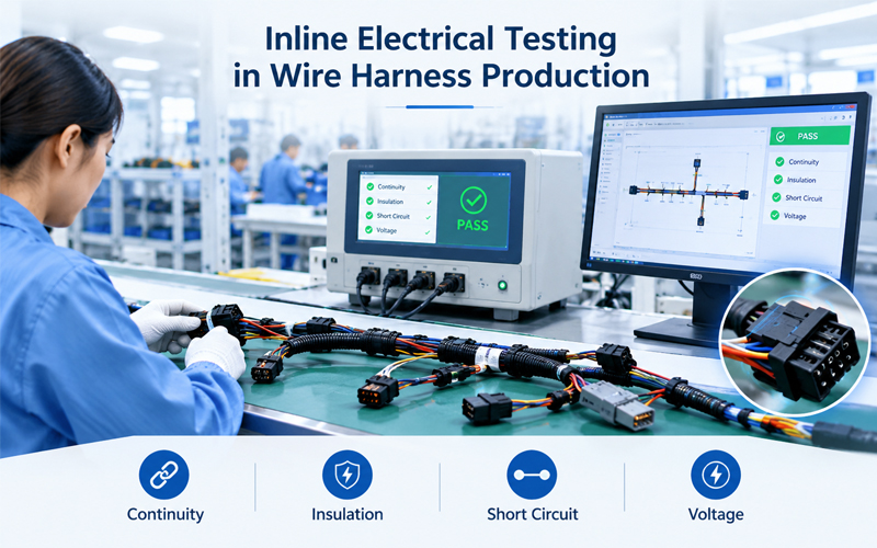
1.What Is Inline Electrical Testing?
Inline electrical testing is the integration of electrical verification into a manufacturing workflow rather than relying exclusively on a separate final inspection station.
Depending on the product and production line, testing may take place after wire preparation, terminal processing, connector assembly, or final harness assembly.
Typical test functions include:
- Open-circuit detection
- Short-circuit detection
- Pin-to-pin continuity verification
- Wiring sequence verification
- Resistance measurement
- Insulation resistance testing
- High-potential dielectric testing, where required
Not every production line requires all these tests. The appropriate test strategy depends on the electrical design, operating voltage, customer specifications, and product risk.
For example, a simple point-to-point control harness may primarily require continuity and wiring verification. A high-voltage cable assembly may require additional insulation-related testing and specific safety controls.
The key principle is to match each test to a defined quality requirement.
2.How Inline Testing Fits Into Wire Harness Production
A typical wire harness manufacturing workflow may include:
Wire Cutting → Stripping → Crimping → Connector Assembly → Inline Electrical Test → Final Inspection → Shipment
The exact sequence varies by product.
Some manufacturers test selected subassemblies before final integration. Others use inline electrical checks at critical stations and retain a comprehensive end-of-line test for the completed harness.
These approaches serve different purposes.
Inline testing helps identify defects during production, while final testing verifies the electrical characteristics of the completed assembly against its defined test requirements.
For complex harnesses, a combined strategy is often more effective than relying on either method alone.
3.Benefits of Inline Electrical Testing
3.1 Earlier Detection of Wiring Errors
The primary benefit of inline testing is the opportunity to detect electrical defects before they move through additional manufacturing stages.
Potential defects include:
- Missing electrical connections
- Incorrect wire-to-pin assignments
- Short circuits between conductors
- Incorrect connector cavity wiring
- Misassembled circuits
- Resistance values outside defined limits
If a wiring error is identified immediately after the relevant assembly operation, the product can be isolated before additional labor and materials are invested.
This can reduce rework costs and prevent defective subassemblies from entering downstream processes.
3.2 Reduced Downstream Rework
A defect found late in production may require disassembly, connector replacement, wire removal, or extensive troubleshooting.
Inline testing can shorten the distance between defect creation and defect detection.
For example, if a connector assembly is wired incorrectly, testing immediately after connectorization may make it easier to identify the affected operation and correct the issue before protective coverings or additional components are installed.
The benefit depends on whether the test station can identify the defect clearly and whether the production workflow supports controlled rework.
3.3 Improved Process Feedback
Inline testing can provide more than a pass-or-fail result.
When test outcomes are recorded and analyzed, recurring failures may reveal patterns associated with:
- A particular workstation
- A specific production order
- A connector or terminal variant
- A wire preparation process
- A recurring assembly error
- A test fixture or contact problem
This information can support corrective action and process improvement.
However, electrical test data alone does not always identify the root cause. It should be evaluated alongside material records, assembly instructions, tooling information, and inspection results.
3.4 Better Production Traceability
When testing equipment is connected to a Manufacturing Execution System (MES) or another production management platform, test results can be linked to relevant production information.
Depending on the system configuration, records may include:
- Product or work-order identification
- Test program version
- Test date and time
- Test station identification
- Pass/fail result
- Measured values
- Failure code
- Retest or rework status
This creates a more useful quality record than a test result that cannot be traced to a specific product or production order.
3.5 Support for Automated Manufacturing
Inline testing can complement automated wire processing and assembly equipment.
For example, a production line may combine automatic wire cutting and stripping, terminal crimping, connector insertion, and electrical verification.
The electrical test station acts as a quality gate within this workflow.
If a defect is detected, the manufacturing system may stop the affected process, reject the unit, or direct it to a controlled rework area.
Such actions must be deliberately designed and validated; they do not occur automatically simply because testing equipment is installed.
4.Which Electrical Defects Can Inline Testing Detect?
The detection capability depends on the test method, fixture, electrical design, and defined acceptance criteria.
| Test Method | Typical Purpose | Important Limitation |
|---|---|---|
| Continuity testing | Verifies intended electrical paths | May not identify every high-resistance or intermittent defect |
| Open-circuit detection | Identifies missing or interrupted connections | Detection depends on circuit accessibility and test configuration |
| Short-circuit detection | Identifies unintended electrical connections between test points | Some internal or condition-dependent shorts may not appear under the test conditions |
| Pin-to-pin verification | Checks whether connections match the required wiring map | Requires an accurate, correctly configured test program |
| Resistance measurement | Measures resistance against specified limits | Results can be affected by test lead resistance, contact resistance, and measurement setup |
| Insulation resistance testing | Evaluates insulation resistance between defined conductors or circuits | Does not prove every aspect of insulation integrity or long-term durability |
| HiPot testing | Evaluates dielectric withstand under specified conditions | Requires an approved test method and appropriate safety controls |
These methods are not interchangeable. A continuity test cannot replace insulation resistance testing, and neither automatically replaces dielectric withstand testing when the product specification requires it.
5.Continuity Testing: Essential but Not Sufficient
Continuity testing is one of the most common electrical checks used in wire harness manufacturing.
The test verifies that intended electrical paths are present between defined connection points.
It can help identify open circuits, missing connections, and certain wiring errors.
However, a basic continuity result does not necessarily prove that a connection has sufficiently low resistance for its intended application.
For example, a poorly formed crimp may still conduct enough current for a basic continuity test to pass, even though the connection does not meet the required mechanical or electrical performance criteria.
The detection threshold matters.
A test system that simply reports whether a circuit is open or closed provides different information from one that measures resistance against a defined limit.
For applications where connection resistance is critical, the test plan should specify the appropriate measurement method and acceptance limits.
6.Insulation Resistance and HiPot Testing Need Separate Consideration
Continuity and short-circuit testing primarily evaluate electrical paths under the conditions of the test.
They do not establish that insulation can withstand the required voltage stress.
Depending on the product design and customer requirements, additional tests may include:
Insulation resistance testing: Measures resistance between specified conductors or between conductors and a reference point under defined test conditions.
HiPot testing: Applies a specified test voltage to evaluate dielectric withstand between designated electrical points.
These tests require careful definition of test voltage, duration, connection points, acceptance criteria, and safety controls.
Not every harness requires every test. Test selection should follow the applicable product specification, engineering assessment, and customer requirements.
For assemblies containing electronic components, suppressors, capacitors, sensors, or other sensitive devices, the test configuration must also account for component limitations. An unsuitable test voltage or connection arrangement may damage the assembly.
7.Limitations of Inline Electrical Testing
Inline testing provides valuable information, but it has important limitations.
7.1 It Cannot Detect Every Mechanical Defect
Electrical tests are not a substitute for mechanical inspection.
Depending on the defect, an electrically passing harness may still contain:
- Incorrect crimp geometry
- Insufficient crimp pull strength
- Damaged insulation
- Poor strain relief
- Inadequate terminal retention
- Incorrect connector locking
- Improper sealing
- Physical damage to the cable
Some mechanical defects may eventually cause electrical failures, but they may not be detectable during a standard electrical test.
Therefore, crimp inspection, terminal retention checks, visual inspection, and other applicable mechanical verification remain important.
7.2 Intermittent Faults May Be Difficult to Detect
Some defects occur only under specific conditions.
Examples include connections that fail during vibration, conductors that break when flexed, or contacts that become unstable after thermal cycling.
A stationary continuity test may pass if the electrical path is intact at the moment of measurement.
Where the application demands it, additional validation may be required, such as flex testing, vibration testing, thermal cycling, or application-specific functional testing.
7.3 Test Fixture Contact Can Affect Results
Inline electrical testing relies on reliable contact between the test equipment and the harness.
Worn probes, contaminated contacts, poor fixture alignment, or incorrect connector adapters can create false failures or inconsistent readings.
This can lead to unnecessary rework, production delays, or incorrect conclusions about product quality.
Fixture maintenance and periodic verification should therefore be part of the test-control plan.
7.4 Incorrect Test Programs Can Create False Confidence
Automated testing depends on correct test programs and wiring definitions.
If the wrong program is selected, the pin map is inaccurate, or acceptance limits are incorrectly configured, the system may fail to detect a genuine defect.
Program control should include version management, verification against approved drawings, authorization for changes, and appropriate validation before release to production.
7.5 Testing Every Unit Does Not Guarantee Zero Defects
Even if every finished harness passes its defined electrical test, that does not prove the product is free from every possible defect.
The test only evaluates the characteristics it is designed and configured to measure, under the conditions applied.
Reliable manufacturing still requires process control, inspection, correct materials, suitable tooling, and product-specific validation.
8.Inline Testing vs. Final Electrical Testing
The two approaches have different purposes and can complement one another.
| Factor | Inline Electrical Testing | Final Electrical Testing |
|---|---|---|
| Primary objective | Detect selected defects during production | Verify the completed assembly |
| Timing | At defined manufacturing stages | After final assembly or at the designated final test stage |
| Main advantage | Earlier feedback and potentially lower rework costs | Evaluates the assembled product at a later quality gate |
| Test scope | Often focused on a specific process or subassembly | Can cover the complete specified wiring map and electrical requirements |
| Main limitation | Cannot verify operations or characteristics not included in the test | Defects are detected later, potentially increasing rework |
| Best application | Process-specific defect prevention and control | Final product verification before release |
The most suitable strategy depends on product complexity and risk.
For a complex harness, testing after connectorization may catch wiring errors before the harness is fully wrapped or enclosed. A final test can then verify the completed wiring configuration before shipment.
9.How to Integrate Inline Testing Into Production
A successful implementation starts with the manufacturing process and the product’s quality requirements, not simply the purchase of a test machine.
Step 1: Define Critical Electrical Characteristics
Identify which defects must be detected at each manufacturing stage.
Determine whether the process requires continuity, short-circuit detection, resistance measurement, insulation resistance testing, HiPot testing, or a combination of methods.
Step 2: Choose the Appropriate Test Point
Position the test station where it can detect relevant defects early without creating unnecessary handling or process delays.
The best location may differ between simple cable assemblies and complex multi-branch harnesses.
Step 3: Validate the Test Fixture
Confirm that the fixture provides reliable contact, correct pin mapping, appropriate accessibility, and repeatable measurement performance.
Step 4: Verify the Test Program
Compare the programmed wiring map and acceptance limits with approved product documentation.
Control program revisions and ensure the correct program is selected for each product variant.
Step 5: Define Failure Handling
Determine what happens when a harness fails.
The process should define product identification, isolation, diagnosis, authorized rework, retesting, and final release.
A failed unit should not return to normal production flow without completing the required disposition process.
Step 6: Connect Test Results to Production Records
Where appropriate, integrate test data with MES or production management systems.
This can help associate test results with the work order, station, product identifier, and relevant manufacturing history.
Step 7: Monitor Test-System Performance
Review false-failure rates, repeated defects, fixture condition, test program revisions, and station downtime.
This helps distinguish genuine product defects from problems caused by the test system itself.
10.How Inline Testing Supports Continuous Improvement
The value of inline electrical testing increases when test results are used to improve the manufacturing process.
For example, repeated open-circuit failures at a particular assembly station may indicate a wiring, terminal insertion, or process-control problem.
Repeated resistance failures may require investigation of crimp quality, contact condition, conductor selection, or measurement setup.
A structured improvement cycle can follow this sequence:
Test Result → Failure Classification → Root-Cause Investigation → Corrective Action → Process Verification
The objective is to identify and reduce recurring defects rather than simply rejecting failed units.
For manufacturers using MES, relevant test data can also be combined with material traceability, process records, and inspection results to support more effective quality analysis.
11.Practical Recommendations for Wire Harness Manufacturers
To gain the most value from inline electrical testing:
- Match each test method to a clearly defined quality requirement.
- Test at stages where defects can be detected and corrected efficiently.
- Maintain approved wiring maps and test program revisions.
- Verify test fixtures and electrical contact reliability.
- Establish clear failure, rework, and retest procedures.
- Combine electrical testing with visual and mechanical inspection.
- Use resistance and insulation-related tests when required by the application.
- Record relevant test results for traceability and analysis.
- Retain final testing where required by the product specification or customer quality plan.
For customized wire harness projects, the test strategy should be defined early enough to account for connector accessibility, circuit architecture, production volume, fixture design, and customer acceptance requirements.
Inline Electrical Testing at FPIC
For customized wire harness manufacturing, electrical verification is an important part of the overall quality-control process.
FPIC supports wire harness projects with production process control, electrical testing, inspection, and traceability activities aligned with applicable product requirements.
The appropriate test configuration depends on the harness design, electrical characteristics, customer specifications, and intended application. Combining suitable electrical tests with mechanical inspection and process validation helps provide a more complete assessment of assembly quality.
The goal is not simply to make testing faster. It is to detect relevant defects at the right stage and maintain a consistent, documented approach to product verification.
Conclusion
Inline electrical testing can improve wire harness manufacturing by identifying selected electrical defects earlier, reducing downstream rework, supporting process feedback, and strengthening traceability.
However, its effectiveness depends on the test method, fixture design, program accuracy, and defect types being evaluated.
Inline testing is most effective when it complements—not replaces—final electrical verification, mechanical inspection, and process control.
By selecting the right test points, maintaining reliable equipment, controlling test programs, and analyzing failure data, manufacturers can build a more effective electrical quality-control strategy.
FAQ
What is inline electrical testing in wire harness production?
Inline electrical testing integrates electrical verification into selected manufacturing stages. It can help identify wiring errors, open circuits, short circuits, and other defined electrical defects before the harness reaches later production stages.
What defects can inline electrical testing detect?
Depending on the test method, it can detect open circuits, short circuits, incorrect pin-to-pin connections, and resistance values outside specified limits. Insulation resistance and HiPot tests can evaluate additional electrical characteristics when required.
Can continuity testing guarantee wire harness quality?
No. Continuity testing verifies electrical paths under the conditions applied, but it does not guarantee correct crimp strength, terminal retention, sealing, insulation durability, or performance under vibration and temperature changes.
What is the difference between inline and final electrical testing?
Inline testing provides process-specific checks during manufacturing, while final electrical testing verifies the completed assembly against the applicable test requirements. The two methods can complement each other.
Does every wire harness need HiPot testing?
No. HiPot testing should be selected according to the product design, electrical requirements, customer specifications, and applicable standards. Test conditions must also protect any sensitive components in the assembly.
How can MES improve inline electrical testing?
MES can associate test results with production orders, product identifiers, test programs, and manufacturing records. This improves traceability and supports failure analysis, rework control, and continuous improvement.
Looking for reliable testing and quality control for customized wire harness assemblies?
FPIC supports customized wire harness projects with engineering coordination, production process control, electrical testing, inspection, and traceability.
Contact our team to discuss your harness design, testing requirements, and production needs.
Resources
- IPC/WHMA-A-620F – Requirements and Acceptance for Cable and Wire Harness Assemblies: Industry standard covering workmanship, processes, testing, and acceptance requirements for cable and wire harness assemblies.
- IPC – Meet Your Standards: Official IPC resource for information about industry standards relevant to electronics manufacturing and cable assembly quality.
- IPC – IPC/WHMA-A-620 Endorsement Program: Provides information about cable and wire harness assembly training and the standard’s coverage of testing, crimp terminations, connectorization, and related manufacturing activities.
- IPC – IPC/WHMA-A-620F Standard Information: Provides an overview of the standard’s role in wire harness manufacturing, process control, inspection, and acceptance.
- IPC – Cable and Wire Harness Standards: Lists relevant IPC standards for cable and wire harness design, manufacturing, and quality requirements.