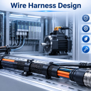
Wire Harness Design Considerations for Compact Industrial Equipment
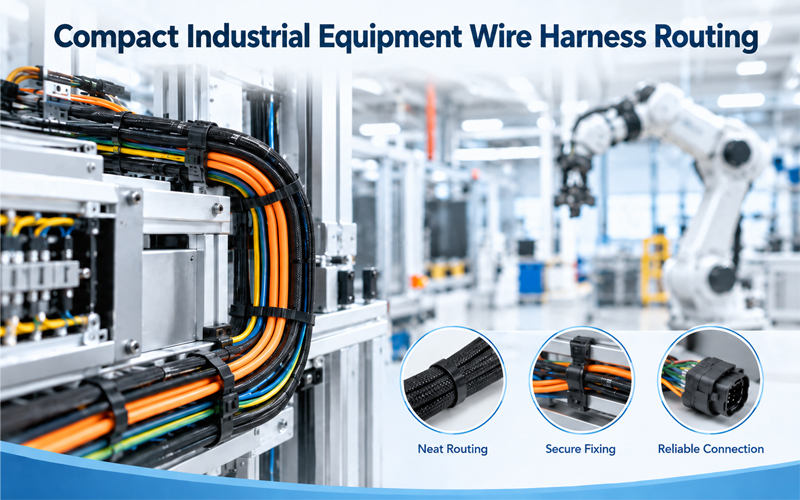
Modern industrial equipment is becoming smaller while offering more functions, sensors, communication interfaces, and control capabilities. As equipment becomes more compact, the wire harness has to fit into increasingly limited spaces without compromising electrical performance, mechanical reliability, or serviceability.
In a large machine, engineers may have sufficient space to route cables around components. In compact industrial equipment, every millimeter can matter. Connectors compete for clearance with circuit boards, motors, cooling systems, mounting brackets, and mechanical assemblies. At the same time, wires must still maintain appropriate bend radius, strain relief, separation, and protection.
For this reason, compact equipment wire harness design requires more than simply reducing cable length. The harness must be designed as part of the overall mechanical and electrical architecture.
Why Compact Equipment Creates Harness Design Challenges
Compact industrial equipment may include PLCs, sensors, motors, actuators, power supplies, communication modules, displays, and control boards within a relatively small enclosure.
This creates several design challenges:
- limited routing space
- tight connector clearance
- small bending areas
- higher wire density
- potential interference between power and signal circuits
- difficult access for assembly and maintenance
- increased risk of abrasion near mechanical structures
A harness that is acceptable in a larger enclosure may become difficult to manufacture or service when the same architecture is compressed into a smaller footprint.
The objective should therefore be controlled integration, rather than simply minimizing harness volume.
1.Start Harness Design With the Equipment Architecture
One of the most effective ways to improve compact harness design is to define routing architecture before the mechanical layout is finalized.
Instead of asking only where the wires can fit, engineers should first identify:
- power entry points
- control boards
- sensor locations
- motor and actuator interfaces
- communication ports
- grounding points
- service-access areas
The harness can then be divided into logical branches based on function and destination.
This approach helps prevent a common problem in compact equipment: a harness that technically fits but creates unnecessary crossovers, excessive bends, or difficult assembly sequences.
Design Around Functional Zones
A compact machine can often be divided into functional zones such as:
- power zone
- control zone
- sensing zone
- communication zone
- external interface zone
Routing each harness branch according to these zones can reduce unnecessary cable length and simplify installation.
It also makes future troubleshooting easier because technicians can understand the function of each branch without tracing the entire harness.
2.Control Bend Radius in Tight Spaces
When space is limited, designers may be tempted to force cables into very small bends. This can create mechanical stress and reduce cable life.
Bend radius should be considered at the beginning of routing rather than after the path has already been selected.
Critical areas include:
- connector exits
- enclosure corners
- cable clamps
- branch points
- PCB interfaces
- panel pass-throughs
The cable should transition smoothly rather than being forced into an abrupt direction change.
Avoid Excessive Stress at Connector Exits
The area immediately behind a connector is particularly important.
If the harness bends sharply as soon as it leaves the connector, mechanical stress can be transferred directly to the terminals and crimped connections. Over time, this may contribute to conductor fatigue, insulation damage, or intermittent electrical problems.
A suitable backshell, strain relief, guide, or controlled routing feature can help distribute mechanical stress more effectively.
Connector backshell solutions are also commonly used to support sealing and strain relief at the cable exit.
3.Optimize Connector Orientation
In compact equipment, connector selection and orientation are closely connected to harness routing.
A connector may have excellent electrical performance but still be unsuitable if its cable exit direction creates a routing conflict.
Engineers should consider:
- straight versus right-angle cable exits
- connector height
- mating direction
- locking mechanism access
- cable bend area
- service clearance
Right-angle or space-efficient termination solutions can sometimes reduce bend stress and improve clearance in confined enclosures.
Connector orientation should therefore be considered during mechanical design, rather than treated as an assembly detail.
4.Separate Power, Signal and Communication Circuits
Compact equipment often places power and signal circuits very close together. This can create challenges related to electromagnetic interference and signal integrity.
Power cables carrying higher currents can generate electromagnetic fields that affect nearby sensitive circuits, especially low-level sensor signals and high-speed communication lines.
Where appropriate, harness architecture should consider:
- physical separation
- shielded cables
- twisted-pair construction
- controlled routing
- grounding strategy
- appropriate shield termination
The exact approach depends on the equipment architecture and signal type. High-speed communication circuits require particular attention because routing geometry, impedance, shielding, and crosstalk can affect signal quality.
The goal is not necessarily to separate every wire physically, but to establish a deliberate routing strategy based on electrical function.
5.Reduce Harness Volume Without Creating New Problems
Miniaturization is an important objective in compact equipment, but reducing harness size requires engineering trade-offs.
A smaller harness may provide:
- better packaging efficiency
- lower material usage
- easier installation
- improved airflow around components
However, excessive miniaturization may create problems such as:
- insufficient bend radius
- inadequate current capacity
- reduced mechanical protection
- difficult connector handling
- limited service access
- higher assembly sensitivity
The best design is not necessarily the smallest harness. It is the harness that achieves the required electrical and mechanical performance within the available space.
Use Branching Strategically
Instead of creating one large cable bundle, strategically positioned branch points can reduce congestion.
However, branch locations should not be placed randomly. They should correspond to actual equipment architecture and installation sequence.
A well-positioned branch can make the harness easier to install, while a poorly positioned branch can create a concentrated stress point.
6.Design for Assembly, Not Just CAD Fit
A harness can look perfect in a 3D model and still be difficult to manufacture.
Compact equipment creates little tolerance for assembly mistakes. If the operator has to force a connector into position or bend a harness around another component during installation, production consistency will suffer.
Design reviews should therefore consider:
- connector insertion direction
- operator hand clearance
- harness pre-assembly options
- clip and fastener accessibility
- wire identification
- installation sequence
- possibility of incorrect routing
Error-proofing features such as polarization, keying, and pre-terminated cable assemblies can help reduce wiring mistakes and simplify installation.
The harness should be designed so that the correct installation path is also the easiest installation path.
7.Protect Harnesses From Abrasion and Mechanical Interference
Space constraints increase the possibility of contact between the harness and surrounding hardware.
Potential risk areas include:
- sheet-metal edges
- mounting screws
- moving mechanisms
- cooling fans
- hinges
- motors
- brackets
- enclosure openings
A harness should not rely on insulation alone to withstand continuous mechanical contact.
Depending on the application, protection may include:
- corrugated tubing
- braided sleeving
- protective tape
- grommets
- edge protection
- clips
- overmolded sections
The protection method should match the expected movement, temperature, environmental exposure, and maintenance requirements.
8.Consider Serviceability Before Finalizing the Layout
Compact equipment often creates a conflict between packaging efficiency and service access.
A harness can occupy very little space while making maintenance extremely difficult.
For example, a connector may be technically accessible but require the removal of several unrelated components before it can be reached.
This is poor service design.
Keep Critical Interfaces Accessible
Frequently serviced or safety-related interfaces should have sufficient access for:
- connector mating and unmating
- visual inspection
- electrical testing
- replacement
- troubleshooting
Where possible, harness branches should be designed so that one failed component does not require removal of the entire harness.
Use Clear Identification
Labels should remain visible after installation whenever practical.
Useful identification methods include:
- wire numbers
- branch labels
- connector IDs
- color coding
- circuit identification
- service markers
Good identification can significantly reduce troubleshooting time in dense industrial equipment.
9.Manufacturing Quality Becomes More Important as Harness Density Increases
The more compact the harness becomes, the less tolerance there is for manufacturing variation.
Crimp quality, wire preparation, terminal insertion, connector locking, labeling, and harness dimensions all need to remain consistent.
IPC/WHMA-A-620 provides requirements and acceptance criteria for cable and wire harness assemblies, including areas such as terminations, strain relief, securing, marking, protective coverings, and finished assembly installation.
For compact equipment, process consistency is especially important because an assembly variation that is acceptable in a large machine may create interference when space is tightly controlled.
This makes design-for-manufacturing an important part of harness development.
10.Validate the Harness in the Actual Equipment
A harness should not be validated only as an independent assembly.
The final equipment environment can introduce mechanical and electrical conditions that are not visible during bench testing.
Validation should consider:
- connector mating and retention
- continuity
- insulation resistance
- mechanical routing
- bend radius
- vibration
- temperature
- abrasion
- EMI/EMC behavior where applicable
- service access
The installed harness should be inspected through the complete equipment operating range.
For compact systems, particular attention should be paid to areas where the harness passes close to moving parts, heat sources, sharp edges, or other cables.
11.A Practical Design Workflow for Compact Wire Harnesses
A structured workflow can help engineers avoid late-stage redesign.
Step 1: Map the Equipment Architecture
Identify all electrical interfaces, mechanical constraints, and service zones.
Step 2: Classify Circuits
Separate power, control, sensor, communication, and safety-related circuits.
Step 3: Define Connector Locations
Select connector types and orientations based on available space and maintenance requirements.
Step 4: Build the Primary Routing Paths
Establish major harness paths before adding secondary branches.
Step 5: Check Bend Radius and Clearance
Review every connector exit, corner, branch point, and enclosure pass-through.
Step 6: Add Protection and Retention
Define clamps, clips, sleeving, grommets, strain relief, and other protective features.
Step 7: Review Assembly and Serviceability
Confirm that operators can install the harness and technicians can access critical interfaces.
Step 8: Prototype and Validate
Build a representative harness and test it in the actual equipment environment.
This workflow helps move harness design from a late-stage packaging exercise to an integrated engineering process.
How FPIC Supports Compact Industrial Wire Harness Projects
For compact industrial equipment, the harness often needs to satisfy several requirements at the same time: limited installation space, controlled routing, reliable connections, mechanical protection, and efficient assembly.
FPIC supports custom wire harness and cable assembly development for industrial applications, including connector integration, branch configuration, cable selection, assembly, and production support.
By reviewing the harness together with the equipment’s mechanical and electrical requirements, the development process can address routing, serviceability, and manufacturing feasibility before the design reaches mass production.
Final Thoughts
Compact industrial equipment creates a unique challenge for wire harness engineers. The goal is not simply to fit more wires into less space.
A reliable compact harness must balance:
- electrical performance
- bend radius
- connector accessibility
- EMI considerations
- mechanical protection
- manufacturing consistency
- serviceability
The best harness designs are developed together with the equipment architecture. When routing, connector orientation, protection, and service access are considered early, engineers can reduce redesign, improve assembly efficiency, and create more reliable equipment.
For compact industrial systems, good harness design is ultimately about using limited space without compromising reliability.
FAQ
What are the main challenges of wire harness design for compact industrial equipment?
The main challenges include limited routing space, tight bend radii, connector clearance, EMI control, mechanical protection, assembly access, and serviceability.
How can a wire harness fit into a compact enclosure without reducing reliability?
Engineers should optimize routing, connector orientation, branch locations, protection, and cable selection rather than simply reducing cable dimensions. The design must maintain appropriate bend radius and mechanical clearance.
Why is connector orientation important in compact equipment?
Connector orientation determines the direction in which the cable exits the interface. A suitable orientation can reduce bend stress, improve clearance, and make installation and maintenance easier.
How should power and signal wires be routed?
Power, sensor, and communication circuits should be routed according to their electrical characteristics. Physical separation, shielding, twisted-pair construction, and appropriate grounding may be used where the application requires additional EMI control.
How can wire harness serviceability be improved?
Critical connectors should remain accessible, branches should follow logical equipment functions, and harnesses should use clear identification. Modular or pre-assembled sections can also simplify maintenance.
What standard is commonly used for wire harness workmanship and acceptance?
IPC/WHMA-A-620 is a widely recognized standard covering requirements and acceptance criteria for cable and wire harness assemblies. Specific customer, industry, and application requirements should also be considered.
Need a Custom Wire Harness for Compact Industrial Equipment?
If your equipment has limited internal space, complex routing requirements, or demanding service conditions, harness design should be considered early in the development process.
FPIC provides custom wire harness and cable assembly solutions for industrial applications, supporting connector integration, routing requirements, prototype development, and production needs.
Contact FPIC to discuss your equipment layout, drawings, or custom harness requirements.
Resources
- IPC/WHMA-A-620 – Requirements and Acceptance for Cable and Wire Harness Assemblies: provides internationally recognized requirements and acceptance criteria for cable and wire harness assemblies, including termination, securing, marking, protection, and installation.
- IPC – Wire Harness Industry Standards: provides information about IPC standards related to wire harness design, assembly, inspection, and quality requirements.
- Molex – Custom Cable Assembly Solutions: provides examples of custom wire harness development, connector integration, overmolding, strain relief, and cable assembly support.
- Molex – PLC Cables and Connectors: discusses connectivity considerations for compact industrial automation equipment, including clearance, connector selection, wiring errors, and serviceability.
- TE Connectivity – Heavy-Duty Sealed Connector Backshells: explains how backshells can provide cable-exit protection, strain relief, and sealing support in demanding industrial environments.