Wire Harness Branch Point Tolerance: Why It Matters
A wire harness branch point tolerance controls where one or more legs leave the main trunk. It matters because correct overall length does not uniquely define the shape of a multi-branch harness. If a breakout shifts along the trunk, one connector may still reach while another becomes short, crosses a bracket, misses a clamp, or pulls sideways on its mating interface. The harness can pass electrical testing and a simple end-to-end length check but still fail during equipment assembly.
For industrial machinery, control cabinets, automation systems, and other space-constrained equipment, fit depends on the complete harness geometry: trunk segments, branch locations, breakout lengths, connector orientation, clip and grommet positions, protective materials, and the three-dimensional route. These characteristics need to be defined on the drawing, translated into controlled assembly instructions, and verified under a repeatable measurement condition.
Why Correct Overall Length Does Not Guarantee Correct Fit
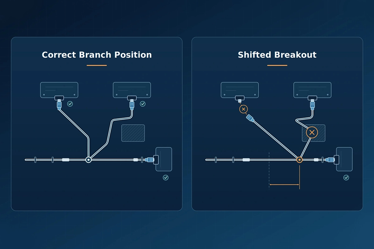
Consider a simple Y-shaped harness. The path from the first connector to a branch connector contains two dimensions:
Connector A to breakout + breakout to Connector B = total path length
The same total can be created from different combinations. If the first segment is 15 mm too long and the branch is 15 mm too short, an end-to-end check may still show the expected total. The internal node, however, has moved 15 mm. That shift can place the breakout on the wrong side of a clamp or leave the short branch unable to follow its intended route.
The problem grows with each additional branch. A multi-branch assembly is better understood as a network of segments and nodes, not as one long cable. Every functionally important node needs its own relationship to the equipment:
| Harness feature | Installation relationship |
|---|---|
| Main trunk | Follows the approved path through the machine or cabinet |
| Branch point | Aligns with the location where circuits separate toward different components |
| Breakout leg | Reaches its connector without being pulled tight or leaving uncontrolled excess |
| Connector | Mates in the required direction and clocking position |
| Clip or clamp | Matches the equipment mounting feature without relocating the harness |
| Grommet | Seats at the panel opening without shifting adjacent branch geometry |
| Sleeve, conduit, or tape | Ends where protection is required without blocking a fixture or bend |
An overall dimension can confirm one relationship. It cannot confirm all of them.
How a Shifted Branch Point Causes Assembly Problems
Branch-position variation does more than change appearance. It changes how the harness shares length across the equipment and how installation loads enter the assembly.
A connector may not reach its mating point
If a branch begins too late, its available routing length may be insufficient even when the total wire cut length is correct. An assembler may be tempted to straighten a designed bend, bypass a retaining point, or pull on the connector to gain the missing distance. The connector may mate, but the installed harness is no longer in its intended condition.
Excess length can be just as disruptive
A branch that is too long may form an uncontrolled loop, contact a moving component, enter a prohibited clearance zone, or crowd other wiring. Extra length is useful only when the design intentionally provides a service loop and identifies where that allowance should be stored. Random dimensional excess is not a substitute for a designed service feature.
Protection materials may collide with hardware
A sleeve, conduit, heat-shrink transition, tape wrap, or breakout boot occupies physical space. If the breakout moves, the protected section may land inside a clamp, next to a sharp edge, through a bulkhead opening, or in a region that requires flexibility. A harness can therefore have acceptable wire lengths but an unusable protection layout.
Clamps and grommets can redistribute length
The available reach often changes after a clip is locked or a grommet is seated. A branch that appears adequate on a table may become short once the main trunk is constrained to the machine. This is why critical dimensions should be evaluated in the same order and condition that represent installation.
Connector orientation can introduce torsion
Reach alone is not enough. Keyways, latches, backshell exits, and right-angle connectors may need a defined rotational orientation. If connector clocking or branch direction is wrong, the installer must twist the leg to mate it. That twist can load the cable, distort the branch, or move the breakout away from its specified position.
Branch Point, Breakout Length, and Connector Reach Are Different
These terms describe related but separate characteristics:
- Branch point location identifies where a leg separates from the trunk.
- Breakout length is the measured length from a defined breakout datum to a defined endpoint on that leg.
- Connector reach asks whether the terminated branch can follow the installed route and mate without unacceptable tension, interference, or excess.
- Branch direction identifies the intended exit path or angular relationship.
- Connector orientation identifies the required clocking of the mating interface, latch, key, backshell, or cable exit.
A drawing should not assume that everyone defines the breakout point in the same way. One person may measure from the center of the wire split, another from the edge of the tape wrap, and another from the end of a breakout boot. Flexible protection can also compress or shift. The drawing or inspection instruction should show the exact datum and endpoint used for acceptance.
The endpoint needs equal care. Depending on the design, the functional dimension may end at the connector mating face, housing rear edge, backshell datum, terminal end, ring-terminal hole center, clip centerline, or grommet shoulder. “To connector” is not precise enough for repeatable inspection.
What Causes Branch Geometry to Vary in Production?
Some variation begins before the harness reaches the assembly board; other variation is introduced while the bundle is being formed.
Wire cut-length accumulation
Individual circuit lengths must support the complete route through the trunk and each branch. Incorrect cut data, the wrong drawing revision, or a mix-up between similar variants can change where wires naturally divide. Cut length alone, however, does not position the breakout. The assembly method must place those wires into the intended geometry.
Bundle lay and internal wire movement
Wires do not always lie as perfectly straight, independent lines. Twisting, crossing, bundling pressure, and different wire diameters affect the amount of usable length along a route. If internal slack is distributed differently from one assembly to the next, branch endpoints may shift even when the original wires were cut consistently.
Taping, sleeving, and conduit installation
Wrapping tension can compact a bundle. Corrugated conduit and braided sleeving can change effective length as they expand or compress. Heat-shrink and breakout components may also establish a fixed transition. The process sequence and placement references therefore influence final geometry.
Connector and accessory installation
Backshells, seals, boots, clips, and grommets add fixed interfaces. If an inspector measures to a cable exit while the drawing controls the mating face, the result may include an unintended housing-length offset. Accessories also affect how a branch is allowed to bend near its endpoint.
Measurement technique
A flexible harness can give different readings when it is stretched, allowed to sag, forced flat, or routed around pins. Heavy connectors can pull on branches during table measurement. Without a defined datum, layout, and applied tension condition, two careful inspectors can obtain different results from the same assembly.
How to Define Wire Harness Branch Point Tolerance Clearly
The drawing should communicate functional intent without imposing arbitrary precision. ASME Y14.5 provides general principles for stating and interpreting dimensions and tolerances, while harness-specific drawings and acceptance requirements still need to describe the flexible assembly and its measurement condition.
1. Select stable, functional datums
Choose references that can be identified consistently in design, production, inspection, and equipment assembly. Useful examples include a connector mating face, a ring-terminal hole center, a clip centerline, or a grommet seating shoulder. A movable tape edge is usually a weaker datum unless the tape edge itself is a controlled feature.
2. Dimension the harness as segments and nodes
Identify critical trunk segments between connectors, breakouts, clips, and pass-through features. Dimension branch legs from a defined branch datum to a defined endpoint. This makes an internal geometry error visible instead of allowing compensating errors to hide inside one overall measurement.
3. Define the branch-point convention
Show whether the controlled location is the theoretical intersection of branch centerlines, the point where conductors separate, or a feature on a breakout component. Include a detail view when the physical transition is too broad or irregular for one line on the main drawing.
4. Specify direction and connector clocking
Use an orientation view, keyway reference, angular requirement, or mating-interface detail where rotation affects installation. A flat formboard view alone may not define a connector that must rotate out of the drawing plane.
5. State the measurement condition
The inspection instruction should state whether the harness is measured in a free state, on a two-dimensional formboard, in a three-dimensional fixture, or against an equipment mock-up. It should also define whether branches are straightened lightly, routed around specified pins, or left without axial preload.
NASA-STD-8739.4A requires full-size three-dimensional form-layout fixtures for complex harnesses within its scope to verify routing, wire lengths, connector configurations, support, and access. That aerospace requirement is not automatically applicable to every industrial project, but it demonstrates an important principle: when fit is three-dimensional, a single flat length measurement may not be enough.
6. Assign tolerances by function
There is no universal branch tolerance that suits every harness. A branch feeding a nearby sensor between two fixed clips may need tighter positional control than a branch routed through open cabinet space. Tolerance selection should consider installation clearance, harness flexibility, connector access, equipment variation, process capability, inspection method, and cost.
Avoid using a very tight tolerance simply because it looks precise. If the tolerance is narrower than the assembly and measurement process can reproduce, it creates disputes without improving installed function. Conversely, a broad general tolerance may be unsuitable for a feature located between fixed interfaces. Critical dimensions should be identified individually.
Dimensional Inspection Should Reproduce the Design Intent
Inspection begins with a controlled drawing revision and an agreed definition of what is being measured. For a new or changed assembly, first-article inspection should verify more than overall length:
- Confirm the wire list, drawing revision, connector part numbers, accessories, and variant.
- Locate the main datum and place the harness in the specified measurement condition.
- Verify trunk segments, branch-point locations, breakout lengths, clip positions, grommets, labels, and protection boundaries.
- Check connector identity, cavity assignment, branch direction, and connector clocking.
- Confirm that the layout does not require stretching, sharp bending, or forced twisting to meet the inspection references.
- Record the required results and approve the setup before batch production.
For simple cable assemblies, a measuring tape, scale, caliper, and clear fixture may be sufficient. Complex multi-branch harnesses can benefit from a full-size harness board, connector nests, locating pins, clip fixtures, profile templates, or a three-dimensional checking fixture. The tool should support the harness at the intended datums without pulling a nonconforming assembly into an apparently correct shape.
Dimensional inspection also needs a practical sequence. Features that will be hidden by tape, conduit, sleeves, or overmolding should be checked before access is lost. Final inspection can then confirm finished geometry, orientation, protection placement, and workmanship. Electrical testing remains essential for continuity and pinout, but it cannot prove that a breakout is in the correct location.
From Design Review to Repeatable Production
A stable process connects product definition, assembly control, and inspection evidence.
During wire harness R&D and engineering review, the equipment route, installation order, mating interfaces, fixed points, clearances, and service needs should be considered together. A two-dimensional harness drawing may be supported by 3D equipment data, photographs, a sample, or a mock-up when the route is difficult to communicate.
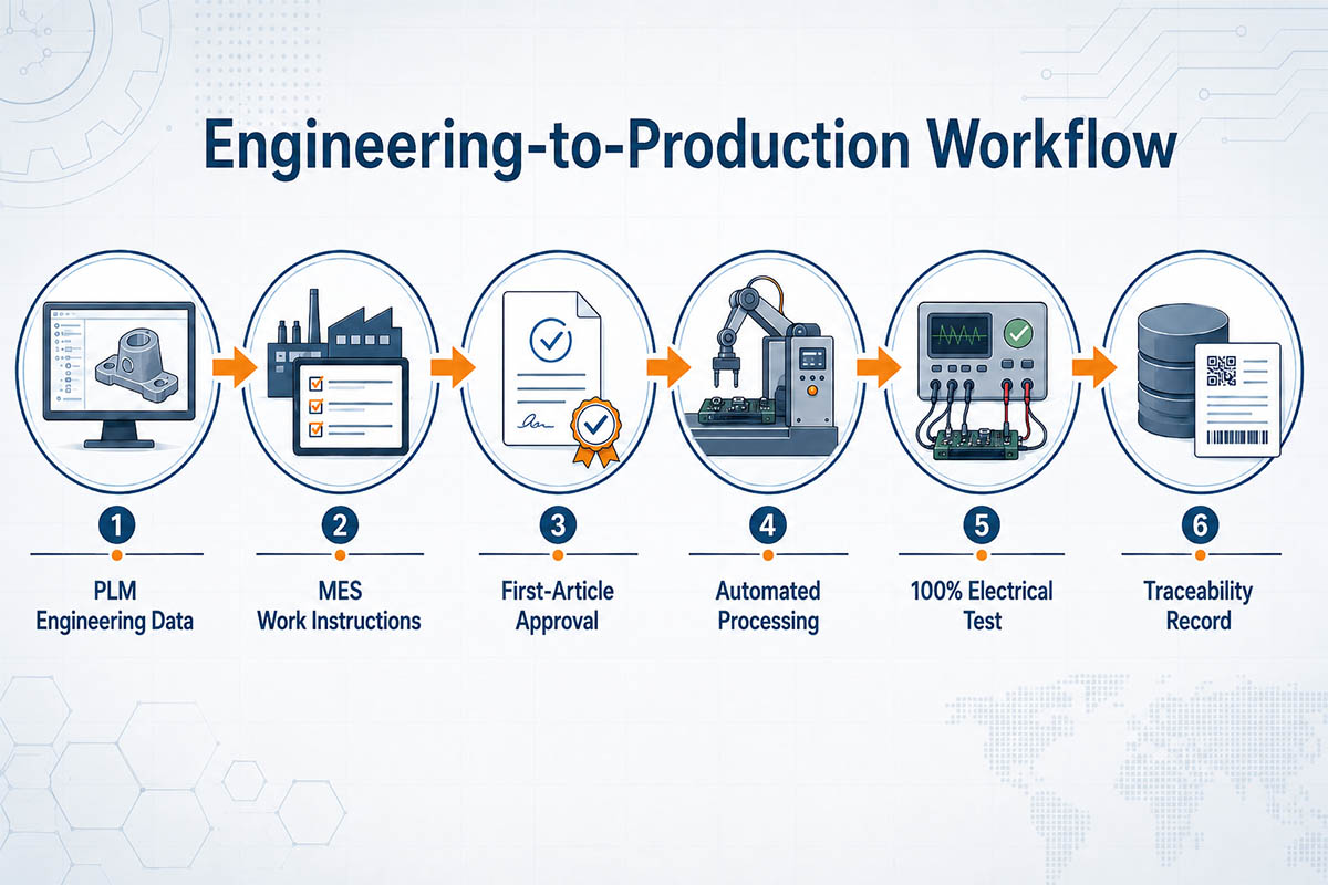
Production documents should translate the approved geometry into usable instructions: wire cut data, harness-board layout, branch identifiers, connector orientation views, clip and sleeve locations, process sequence, and inspection points. Revision control is especially important for harness families that share connectors and colors but use different branch layouts.
FPIC’s manufacturing capability includes wire harness processing, assembly, inspection, testing, and digitally supported production management. Its quality assurance scope includes dimensional and appearance inspection for cable length, branch position, connector interface, terminal position, alignment, and other critical dimensions. The exact inspection method, fixture, tolerance, and records should be agreed for each project.
For industrial equipment wire harnesses, the most useful validation is often an installation trial on the actual equipment or a representative fixture. This can reveal access limitations, clamp-sequence effects, connector-handling space, out-of-plane routing, and interferences that are difficult to see on a flat drawing.
Information to Provide for a Multi-Branch Custom Harness
To evaluate a custom wire harness efficiently, provide as much of the following as possible:
- current 2D harness drawing and revision;
- 3D equipment layout or routing model, when available;
- wiring diagram, wire list, BOM, and pin assignments;
- clearly identified dimensional datums and tolerances;
- connector mating faces, keying, exit direction, and clocking requirements;
- branch, clip, clamp, grommet, label, sleeve, and conduit locations;
- installation order, access constraints, and prohibited routing zones;
- intended service loops and where excess length may be stored;
- applicable workmanship and inspection standards;
- prototype quantity, forecast volume, and required inspection records.
FPIC’s OEM/ODM wire harness service can support requirement evaluation, drawing and material review, prototyping, process planning, inspection, and production transfer within the agreed project scope. If the installed route is critical, include equipment-side reference data rather than supplying only a wire list and overall length.
The Practical Takeaway
A multi-branch harness fits only when its internal geometry matches the equipment. Overall length is one useful characteristic, but it cannot locate a breakout, define a branch direction, control connector clocking, or prove alignment with clips and pass-through points.
Treat the harness as a routed assembly of segments, nodes, and interfaces. Define functional datums, measure branch features under a repeatable condition, verify the first article before production, and validate complex layouts against the real three-dimensional installation. These controls reduce forced assembly, late rework, connector stress, and disputes over whether a flexible harness meets its drawing.
To discuss a new industrial or multi-branch assembly, send FPIC your drawing and installation requirements. Include the equipment layout, critical interfaces, measurement method, required tolerances, quantity, and applicable standards so the project can be evaluated for manufacturing and inspection.
Frequently Asked Questions
What is a wire harness branch point?
A branch point is the location where one or more legs separate from the main harness trunk. The drawing should define how that location is identified and measured because the physical transition may include tape, sleeving, conduit, or a breakout component.
Can overall harness length and branch length both be correct while the harness still does not fit?
Yes. The connector may have the required nominal reach on a flat table but still conflict with a clip, grommet, bracket, bend, or three-dimensional route. Direction, clocking, fixed-point location, and the measurement condition also affect installation fit.
Where should breakout length be measured from?
It should be measured from the datum defined on the approved drawing or inspection instruction. Possible references include a theoretical branch intersection, conductor separation point, tape edge, or breakout feature, but the selected convention must be explicit and repeatable.
Is there a standard tolerance for every harness branch?
No. The appropriate tolerance depends on function, installation clearance, flexibility, fixed interfaces, process capability, measurement method, and the governing customer or industry requirements. Critical branch dimensions should be specified for the actual application.
Why can two inspectors obtain different harness dimensions?
Flexible assemblies change shape when stretched, routed, supported, or allowed to sag. Different datums, connector endpoints, fixture paths, and applied tension can therefore create different readings. A controlled measurement method reduces this variation.
Does electrical testing verify branch-point location?
No. Electrical testing can verify continuity, pinout, shorts, and other defined electrical characteristics, but it does not confirm harness geometry. Branch locations, lengths, orientations, and protective features require dimensional and visual verification.
Resources
- Global Electronics Association (IPC), Meet Your Standards — IPC/WHMA-A-620F: https://www.ipc.org/meet-your-standards
- NASA, NASA-STD-8739.4A with Change 4 — Workmanship Standard for Crimping, Interconnecting Cables, Harnesses, and Wiring: https://standards.nasa.gov/standard/NASA/NASA-STD-87394
- ASME, Y14.5-2018 — Dimensioning and Tolerancing: https://www.asme.org/codes-standards/find-codes-standards/dimensioning-and-tolerancing
- Siemens Digital Industries Software, Formboard Design: https://www.siemens.com/en-gb/technology/formboard-design/
- Autodesk Inventor Help, Nailboard Harness Dimensions: https://help.autodesk.com/cloudhelp/2025/ENU/Inventor-Help/files/GUID-21B611B4-3C4F-46B3-AAFD-0F05401C22BA.htm