Vision Inspection in Wire Harness Manufacturing: Improving Assembly Accuracy
Wire harness manufacturing involves multiple assembly operations where small positioning errors can lead to functional problems, rework, or product rejection. A terminal may not be fully inserted into a connector housing, a seal may be missing, or a wire may be routed incorrectly. Some defects are easy to identify visually, while others require electrical or mechanical testing.
As product configurations become more complex and production requirements increase, manufacturers are increasingly using machine vision to support assembly inspection.
Vision inspection uses cameras, lighting, image processing, and defined inspection criteria to evaluate selected product features. When correctly configured, it can help identify visible assembly defects, standardize repetitive inspections, and provide more consistent quality records.
However, vision systems are not a complete replacement for human expertise or other testing methods. Their effectiveness depends on the defect being inspected, image quality, product variation, inspection coverage, and system validation.
This article explains how vision inspection improves wire harness assembly accuracy and how manufacturers can integrate it into a practical quality-control strategy.
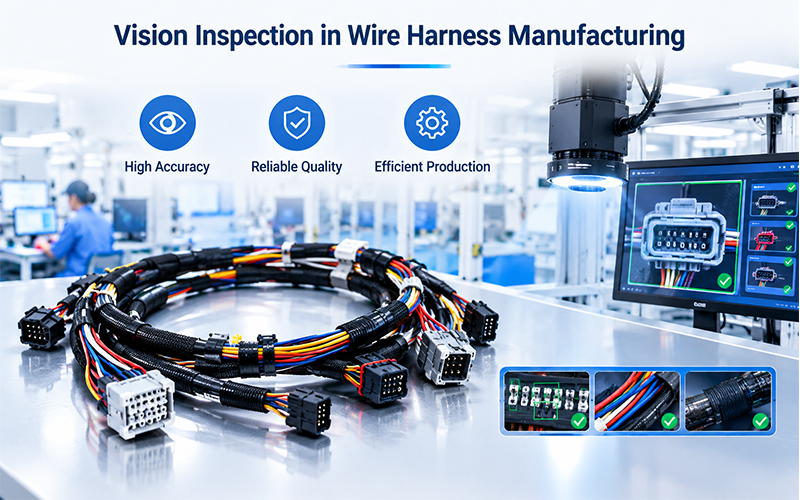
1.What Is Vision Inspection in Wire Harness Manufacturing?
Vision inspection is a method of evaluating products using captured images and image-processing algorithms.
In wire harness manufacturing, a vision inspection system may include:
- Industrial cameras
- Lenses and image sensors
- Controlled lighting
- Image-processing software
- Product positioning fixtures
- Inspection programs
- Pass/fail decision logic
- Data recording and communication interfaces
Depending on the application, the system may use conventional rule-based image processing, pattern matching, measurement tools, or AI-based image analysis.
A simple system might check whether a connector is present and correctly oriented. A more advanced system may inspect multiple terminal positions, verify component presence, compare an assembly with a reference image, or measure visible geometric features.
The inspection scope must be defined according to the actual product requirements.
For example, detecting a visibly missing seal is different from proving that a seal meets its specified compression or waterproofing performance.
2.Why Assembly Accuracy Matters
Wire harnesses often contain multiple wires, terminals, connectors, clips, seals, labels, and protective components.
Even when individual parts meet their specifications, incorrect assembly can compromise the completed product.
Common assembly problems include:
- Missing components
- Incorrect connector orientation
- Incomplete terminal insertion
- Misplaced seals
- Incorrect wire routing
- Missing clips or retainers
- Incorrect label placement
- Visible insulation damage
- Incorrect component combinations
These issues can lead to assembly delays, electrical failures, installation difficulties, or field reliability problems.
Vision inspection helps manufacturers check selected visual characteristics at defined stages of production, allowing certain defects to be detected before the assembly moves to subsequent operations.
3.Key Applications of Vision Inspection
3.1 Terminal Position and Insertion Inspection
Terminal insertion is a critical operation in connectorized wire harness production.
A terminal that is not fully inserted or is positioned incorrectly may fail to establish a reliable connection or may become displaced during handling.
Depending on connector design and camera access, vision systems can inspect visible features such as:
- Terminal presence
- Terminal alignment
- Relative insertion position
- Visible terminal deformation
- Position consistency across multiple cavities
However, terminal retention cannot always be confirmed from a front-facing image. Some connector designs conceal the locking feature, making additional inspection or mechanical verification necessary.
For high-risk applications, visual inspection should be combined with appropriate terminal-retention checks and electrical testing.
3.2 Connector Orientation and Assembly Verification
Connectors may have different keying features, pin counts, orientations, or housing configurations.
When similar components are used within the same production area, selecting the wrong variant can create significant downstream problems.
A vision system can compare visible product features against the expected configuration.
Possible checks include:
- Connector housing type
- Keying or orientation features
- Connector presence
- Housing damage
- Visible locking components
- Assembly position
The system should use approved reference data and account for legitimate differences between product variants.
3.3 Missing Component Detection
Wire harness assemblies may require clips, seals, retainers, protective sleeves, labels, or other accessories.
Missing components can be difficult to identify when production is repetitive or the assembly contains many branches.
Vision inspection can compare the observed assembly with a defined reference and check for selected required components.
This is especially useful when components are visually distinguishable and their inspection positions are repeatable.
If a component is hidden behind another part or located inside a closed housing, a conventional camera may not provide sufficient visibility.
3.4 Wire Routing and Assembly Position
Wire routing affects installation, mechanical protection, and serviceability.
For harnesses with defined branch positions or assembly-board layouts, vision systems can compare the assembled product with expected routing or positional references.
Depending on the setup, the system may identify:
- Incorrect branch placement
- Missing wire segments
- Incorrect clip positions
- Misaligned connectors
- Unexpected wire crossings
- Deviations from defined assembly locations
Flexible wires create a particular challenge because their positions can vary naturally during handling.
Inspection criteria must distinguish acceptable variation from actual assembly defects. A rigid comparison against a single reference image may create false rejects when the product is functionally correct but positioned slightly differently.
3.5 Label and Marking Verification
Product identification is important for manufacturing traceability, installation, and downstream service.
Vision inspection can support checks for:
- Label presence
- Label position
- Label orientation
- Visible printing defects
- Part-number text
- Barcode or QR-code readability
Optical character recognition (OCR) can read printed text, while barcode-reading tools can decode supported machine-readable identifiers.
These functions can help prevent incorrect or unreadable labels from reaching packaging and shipment.
However, reading a label successfully does not necessarily prove that the label belongs to the correct product. Where identification accuracy is critical, the decoded information should be compared with the approved production order or product record.
4.How a Machine Vision Inspection System Works
A typical vision inspection workflow follows several stages.
Image Capture → Image Processing → Feature Detection → Rule Evaluation → Pass/Fail Decision → Data Recording
Step 1: Image Capture
The camera captures the product from a defined position.
Stable positioning and appropriate lighting are essential because reflections, shadows, and changes in product orientation can affect image quality.
Step 2: Image Processing
The system processes the image to identify relevant areas, edges, patterns, shapes, colors, or other visual characteristics.
Step 3: Feature Detection
The inspection software evaluates selected product features, such as the presence of a terminal, the position of a seal, or the location of a label.
Step 4: Rule Evaluation
The measured or detected features are compared against approved criteria.
These criteria may include position tolerances, required component presence, expected patterns, or permitted visual conditions.
Step 5: Pass/Fail Decision
The system determines whether the inspected features meet the defined acceptance criteria.
Failed or uncertain results may require rejection, reinspection, or operator review, depending on the process design.
Step 6: Data Recording
Where supported, the system records inspection results and links them to the relevant production order, product identifier, or workstation.
This provides a foundation for defect analysis and manufacturing traceability.
5.Lighting and Camera Setup Are Critical
A vision system can only analyze the information captured in its images.
Poor lighting, reflections, shadows, or inconsistent product positioning can reduce inspection accuracy.
Important design considerations include:
- Camera resolution
- Lens selection
- Working distance
- Lighting angle
- Surface reflectivity
- Product color variation
- Inspection field of view
- Camera mounting stability
- Product positioning repeatability
For example, metallic terminals may reflect light differently depending on their angle. Transparent or translucent seals may be difficult to distinguish from the surrounding housing.
Diffuse lighting, directional lighting, backlighting, or other techniques may be selected according to the feature being inspected.
The correct configuration should be validated using representative production samples, including acceptable variations and known defect examples.
6.Benefits of Vision Inspection
6.1 More Consistent Repetitive Inspection
Manual inspection can be affected by fatigue, viewing angle, workload, and differences in individual judgment.
A validated vision system applies the same programmed inspection criteria repeatedly.
This can improve consistency for clearly defined visual features, particularly during repetitive, high-volume production.
6.2 Faster Inspection at Selected Stations
Automated image capture and processing can reduce inspection time for certain repetitive checks.
This is useful when a production line needs to verify component presence or positioning without requiring a separate manual inspection for every feature.
Actual cycle time depends on the number of inspection points, image-processing complexity, product handling, and required decision logic.
6.3 Earlier Detection of Assembly Errors
Placing a vision station immediately after a critical assembly operation can help detect certain defects before additional components or protective materials are installed.
For example, inspecting terminal position after connectorization may reduce the need to disassemble a more complete harness later.
The earlier the defect is detected, the easier it may be to isolate the affected process and perform corrective action.
6.4 Improved Inspection Records
When integrated with production management systems, vision inspection can generate records such as:
- Inspection status
- Defect category
- Product or work-order identifier
- Inspection timestamp
- Station identification
- Stored images, where required
- Reinspection or review status
These records can support traceability, defect analysis, and process improvement.
Image storage policies should be defined according to customer requirements, data volume, retention needs, and system capacity.
6.5 Support for Standardized Quality Control
Vision inspection can help standardize checks across workstations and production shifts.
When inspection programs and reference images are properly controlled, the same approved criteria can be applied to repeated production tasks.
This is especially valuable when a manufacturer produces multiple harness variants and needs to maintain consistent inspection methods.
7.Limitations of Vision Inspection
Despite its advantages, vision inspection has important technical limitations.
7.1 Hidden Defects May Not Be Visible
A camera can only inspect features that are visible from its viewing position and accessible to its imaging method.
For example, a terminal may appear correctly positioned from the front while its internal locking feature is not fully engaged.
Likewise, an internal crimp defect cannot normally be verified through an external image of a completed connection.
Additional methods may be needed, including dimensional inspection, crimp cross-section analysis, pull-force testing, or electrical testing.
7.2 Flexible Wires Create Positioning Challenges
Wire harnesses are flexible assemblies.
Branch positions, wire curvature, and cable placement may change slightly during production or handling.
If the inspection system expects every wire to follow exactly the same image pattern, acceptable products may be incorrectly rejected.
A robust system should account for permitted geometric variation while maintaining clear limits for genuine defects.
Fixtures, reference features, controlled product presentation, and appropriately selected image-processing methods can improve repeatability.
7.3 Reflective and Transparent Materials Are Difficult to Inspect
Metallic terminals, glossy connector housings, transparent seals, and dark insulation may create challenging imaging conditions.
Reflections can obscure features, while similar colors or low contrast can make component boundaries difficult to identify.
These issues must be addressed during system design rather than relying only on software adjustments after installation.
7.4 False Rejects and Missed Defects Are Both Possible
A vision system can produce two important types of error:
- False reject: An acceptable product is classified as defective.
- Missed defect: A defective product is incorrectly accepted.
Excessively strict thresholds can increase false rejects, while overly permissive thresholds can allow defects to pass.
The inspection system should therefore be validated against known-good samples, representative defects, normal production variation, and the intended operating environment.
7.5 AI Does Not Remove the Need for Validation
AI-based vision may be useful for complex visual patterns or defects that are difficult to describe using simple geometric rules.
However, performance depends on training data, defect representation, lighting consistency, product variation, and model configuration.
A model that performs well on one product variant may not perform equally well on another.
Any change to the product, camera, lighting, software, or inspection criteria should be evaluated to determine whether revalidation is required.
8.Vision Inspection vs. Electrical Testing
Vision inspection and electrical testing evaluate different characteristics.
| Inspection Method | What It Can Evaluate | Important Limitation |
|---|---|---|
| Vision inspection | Visible component presence, position, orientation, labels, and selected surface defects | Cannot reliably evaluate hidden electrical or mechanical conditions |
| Continuity testing | Whether intended electrical paths are present under defined test conditions | Does not prove all mechanical characteristics or long-term reliability |
| Resistance measurement | Electrical resistance against defined limits | Depends on measurement method, test contacts, and acceptance criteria |
| Insulation resistance testing | Insulation resistance between specified electrical points | Does not prove every aspect of insulation integrity or durability |
| HiPot testing | Dielectric withstand under defined conditions | Requires an appropriate test plan and safety controls |
| Mechanical testing | Selected retention, pull strength, or mechanical performance | Usually evaluates specific characteristics rather than all assembly defects |
These methods are complementary.
For example, a vision system may detect a missing seal, while an electrical tester verifies circuit continuity. Neither result alone proves that the completed assembly meets every mechanical, environmental, and functional requirement.
9.How to Integrate Vision Inspection Into Production
A practical implementation should start with the product and the defects that matter most.
Step 1: Identify Critical Visual Characteristics
List the defects that can be detected visually and that have meaningful consequences for product quality.
Prioritize characteristics such as terminal position, connector orientation, component presence, and label accuracy according to product risk.
Step 2: Define Acceptance Criteria
Specify what constitutes an acceptable and unacceptable result.
Where dimensional tolerances apply, define the measurement method and permitted range. Avoid relying solely on subjective descriptions such as “looks correct.”
Step 3: Select the Inspection Method
Determine whether the application requires conventional image processing, pattern matching, OCR, barcode reading, dimensional measurement, or AI-assisted classification.
The method should match the feature and required detection capability.
Step 4: Design Lighting and Fixtures
Ensure that the target feature can be captured consistently.
Use suitable lighting, stable camera mounting, and repeatable product positioning.
Step 5: Validate Detection Performance
Test the system with known-good samples, representative defect samples, and normal production variation.
Evaluate both missed defects and false rejects rather than measuring speed alone.
Step 6: Define Failure Handling
Specify what happens when an inspection fails or produces an uncertain result.
The process should include product identification, isolation, operator review where appropriate, rework authorization, and reinspection.
Step 7: Connect Inspection Data to Production Records
Where required, connect inspection results with MES or other manufacturing systems.
This allows quality teams to relate defects to production orders, workstations, product variants, and corrective actions.
Step 8: Maintain and Revalidate the System
Monitor lighting condition, lens cleanliness, camera alignment, fixture wear, software revisions, and product changes.
A vision system should remain under controlled maintenance and change management throughout its operating life.
10.Using Vision Inspection to Support Continuous Improvement
The long-term value of vision inspection comes from using inspection results to improve the manufacturing process.
For example, repeated terminal-position failures may indicate an insertion-process issue, an unsuitable fixture, or a variation in component presentation.
Repeated label-reading failures may indicate printing problems, inconsistent label placement, or poor lighting.
A structured improvement process can follow this sequence:
Inspection Result → Defect Classification → Root-Cause Analysis → Corrective Action → Verification
This approach helps manufacturers move beyond rejecting defective assemblies and toward preventing recurring defects.
When vision data is combined with electrical test results, process records, and material traceability, it can provide a more complete picture of production quality.
11.Vision Inspection at FPIC
For customized wire harness projects, assembly accuracy depends on the correct combination of materials, components, work instructions, process controls, and inspection methods.
FPIC supports customized wire harness manufacturing through production process control, inspection, electrical testing, and traceability activities aligned with applicable product requirements.
The appropriate inspection approach depends on the harness structure, connector configuration, production volume, customer specifications, and the risks associated with each assembly operation.
Vision inspection can be used where visible features are suitable for automated verification, while other quality requirements continue to be addressed through appropriate electrical, mechanical, and process-validation methods.
The objective is to establish a practical inspection strategy that improves consistency without relying on any single inspection technology to detect every possible defect.
Conclusion
Vision inspection can improve wire harness assembly accuracy by standardizing repetitive visual checks, detecting selected assembly defects, and supporting traceability.
Its greatest value comes from inspecting the right features at the right production stage, with appropriate lighting, fixtures, acceptance criteria, and validation.
However, visual inspection cannot replace electrical testing, mechanical verification, or application-specific product validation.
A reliable wire harness quality system combines vision inspection, electrical testing, mechanical checks, and controlled manufacturing processes.
When these methods work together, manufacturers can detect more relevant defects, improve assembly consistency, and build a stronger foundation for continuous quality improvement.
FAQ
What is vision inspection in wire harness manufacturing?
Vision inspection uses industrial cameras and image-processing software to evaluate visible product features, such as terminal position, connector orientation, component presence, label placement, and selected surface defects.
What defects can machine vision detect in wire harness assembly?
Depending on the system design, it can detect missing components, visible terminal-position errors, incorrect connector orientation, misplaced seals, labeling problems, and selected wire-routing or appearance defects.
Can vision inspection detect incorrect crimping?
Vision systems may identify certain visible crimp defects when the crimp is accessible and the relevant features can be imaged. However, they cannot reliably verify all internal crimp characteristics. Dimensional inspection, cross-section analysis, pull-force testing, or other appropriate methods may still be required.
Can machine vision replace manual inspection?
It can automate selected repetitive visual checks, but some products and defects still require operator judgment or additional inspection methods. The decision depends on validated detection performance and product requirements.
What is the difference between vision inspection and electrical testing?
Vision inspection evaluates visible features and assembly conditions. Electrical testing evaluates defined electrical characteristics, such as continuity, resistance, insulation resistance, or dielectric withstand. Both may be needed for comprehensive quality control.
How can manufacturers reduce false rejects in vision inspection?
They can improve lighting, stabilize product positioning, define clear acceptance criteria, validate the system using representative samples, and monitor inspection performance. Product changes and system adjustments should be evaluated for their impact on detection capability.
Looking for reliable quality control for customized wire harness assemblies?
FPIC supports customized wire harness projects with engineering coordination, production process control, inspection, electrical testing, and traceability.
Contact our team to discuss your harness design, assembly requirements, and quality expectations.
Resources
- Cognex – Machine Vision: Explains machine vision fundamentals and how automated imaging systems support industrial inspection and manufacturing quality.
- KEYENCE – Machine Vision Systems: Provides information about industrial vision systems, image processing, measurement, and automated inspection applications.
- IPC – Standards: Official resource for electronics manufacturing standards, including standards relevant to cable and wire harness assembly workmanship and acceptance.
- GS1 – Barcode Standards: Provides information on barcode standards that can support product identification and automated label verification.
- NIST – Smart Manufacturing Systems: Covers smart manufacturing systems and data-driven approaches that can support connected inspection and production improvement.