Why Cable Bend Radius Matters in Wire Harness Design
Cable bend radius is one of the most important mechanical design parameters in an industrial wire harness.
A cable may meet the required voltage, current, shielding, and connector specifications but still fail prematurely if it is routed through a bend that is too tight.
This becomes especially important in:
- Industrial automation equipment
- Robotic arms
- Servo systems
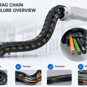
- Drag chains
- CNC machinery
- Moving sensor systems
- Circular cable assemblies
- Repeated-motion applications
The reason is straightforward: bending creates mechanical stress throughout the cable structure.
When the bend radius becomes too small, that stress can affect:
- Copper conductors
- Individual conductor strands
- Core insulation
- Shields
- Fillers
- Outer jackets
- Connector terminations
- Strain-relief structures
For stationary equipment, an excessive bend may cause immediate deformation or long-term material stress.
For dynamic applications, repeated bending can gradually produce conductor fatigue, shield damage, insulation cracking, or failure near the connector exit.
A reliable wire harness design must therefore evaluate bend radius together with cable construction, movement, connector orientation, routing space, and strain relief.
Quick Answer: What Is Cable Bend Radius?
Cable bend radius is the radius of the inside curve formed when a cable is bent. The minimum bend radius is the smallest radius at which that cable can be routed without exceeding its intended mechanical limits.
It is commonly expressed as a multiple of the cable’s outer diameter:
Minimum Bend Radius = Cable Outer Diameter × Specified Factor
However, there is no universal multiplier that applies to every industrial cable.
The correct value depends on:
- Cable construction
- Conductor stranding
- Number of cores
- Shielding structure
- Jacket material
- Cable diameter
- Temperature
- Fixed or moving installation
- Torsional loading
- Manufacturer qualification
Cable manufacturers therefore normally specify separate minimum bending radii in the product datasheet.
HELUKABEL, for example, shows that one drag-chain cable can have a minimum radius of 4 × cable diameter in fixed installation and 7.5 × diameter in moving operation, while some robot and Ethernet cables require substantially larger ratios.
The design rule is therefore:
Use the bend-radius specification for the actual cable and actual application—not a generic rule of thumb.
Why a Smaller Bend Radius Creates More Cable Stress
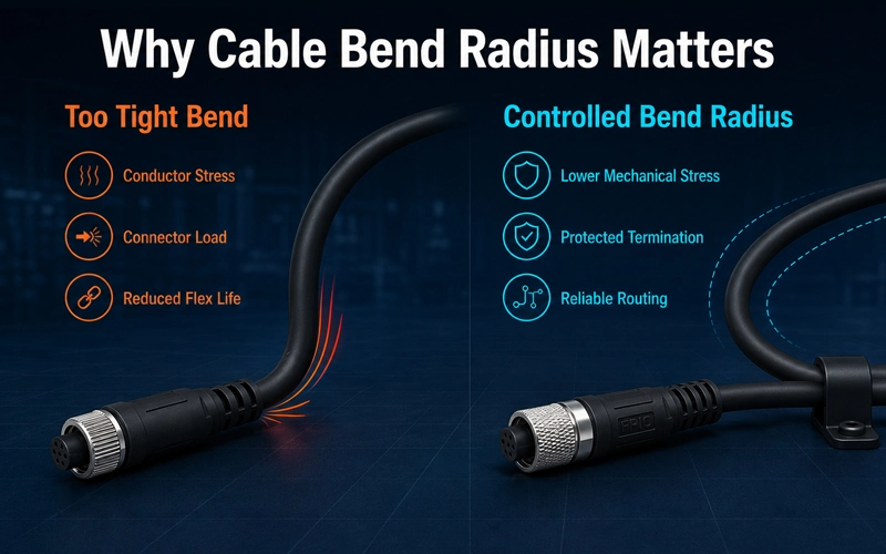
When a straight cable is bent, the materials on the outside of the curve are stretched while those on the inside of the curve are compressed.
The tighter the bend becomes, the greater this difference.
This can produce several mechanical effects.
Outer-Side Tension
Conductors, insulation, shielding, and jacket materials on the outer arc experience tensile stress.
Inner-Side Compression
Materials on the inner arc are compressed and may buckle or shift.
Internal Core Movement
Individual cores can move relative to one another, particularly in multicore cables.
Shield Deformation
Foil or braided shielding may deform when subjected to excessive bending.
Termination Stress
If the bend occurs close to a connector, force may be transferred directly into the terminal, solder joint, crimp, or cable gland.
In a single installation bend, these stresses may remain within acceptable material limits.
In continuous motion, the cable repeatedly changes between tension and compression. This alternating loading is why dynamic applications require more careful cable design.
What Can Happen When Bend Radius Is Too Small?
1. Conductor Fatigue
Copper is flexible, but repeated mechanical deformation can eventually fatigue individual conductor strands.
This risk increases when the cable:
- Bends repeatedly at the same location
- Uses an inappropriate conductor construction
- Operates below its specified bend radius
- Experiences simultaneous tension or torsion
- Is incorrectly restrained inside a cable carrier
As strands gradually break, conductor resistance may increase before a complete open circuit occurs.
This makes bending-related failures particularly difficult because the cable can initially continue operating.
2. Insulation Damage
Insulation must remain intact around each conductor.
An excessively tight bend may cause:
- Compression
- Stretching
- Local thinning
- Cracking
- Separation from the conductor
The risk becomes greater at low temperatures if the insulation material becomes stiffer.
Damage may not be immediately visible from the outer jacket.
For higher-voltage circuits, deterioration of insulation integrity can become an electrical safety concern.
3. Shielding Degradation
Industrial signal, servo, encoder, and communication cables often use shielding to control electromagnetic interference.
Possible shield constructions include:
- Copper braid
- Foil shield
- Combined foil and braid
- Individually shielded pairs
Repeated tight bending can alter shield geometry or damage shield elements.
This may result in:
- Reduced shield coverage
- Increased transfer impedance
- Signal instability
- Increased susceptibility to EMI
A cable can therefore remain electrically continuous while its signal performance deteriorates.
4. Outer Jacket Damage
The outer jacket protects the cable against mechanical and environmental exposure.
Excessive bending can contribute to:
- Cracking
- Flattening
- Wrinkling
- Abrasion
- Local deformation
This is particularly important in drag-chain systems, where the jacket repeatedly contacts the carrier and neighboring cables.
5. Stress at the Connector Termination
One of the most common design problems occurs when the cable is forced to bend immediately after leaving the connector.
The cable may technically remain above its minimum bending radius overall, but the actual stress concentration appears at the connector exit.
This can place load on:
- Crimped terminals
- Solder joints
- Shield terminations
- Cable glands
- Overmolded interfaces
- Connector housings
For this reason, bend radius and connector exit design should be evaluated together.
Static Bend Radius vs. Dynamic Bend Radius
This distinction is essential in industrial wire harness design.
Static Bending
A static cable is bent during installation and then remains substantially stationary.
Examples include:
- Internal machine wiring
- Control cabinets
- Fixed sensor connections
- Permanently routed equipment cables
The cable experiences the bending operation primarily during installation.
Dynamic Bending
A dynamic cable repeatedly moves during equipment operation.
Examples include:
- Drag chains
- Linear axes
- Robotic systems
- Pick-and-place machines
- Automated storage systems
- Moving machine doors
- Servo motor systems
Dynamic cables experience repeated tensile and compressive stress.
Therefore, the specified dynamic bend radius is commonly larger than the permitted fixed-installation radius.
HELUKABEL’s published specifications illustrate this difference: its MULTISPEED 500-C-PVC drag-chain cable specifies 7.5 × outer diameter for flexible use versus 4 × outer diameter for fixed installation.
LAPP similarly advises that cables used for fixed installation, flexible operation, drag chains, and torsional loading require application-specific constructions and should not be treated as interchangeable. It also states that minimum bend radius must be observed in drag-chain applications to avoid cable damage or system failure.
Static vs. Dynamic Cable Design
| Design Factor | Static Installation | Dynamic / Moving Application |
| Cable movement | Mainly during installation | Repeated during operation |
| Bending frequency | Low | Potentially millions of cycles |
| Bend-radius requirement | Often smaller | Usually more conservative |
| Conductor design | Standard flexible construction may be suitable | Fine or extra-fine stranded construction often required |
| Jacket requirement | Based mainly on environment | Must also tolerate repeated flexing and abrasion |
| Shield design | Standard shielding may be suitable | Shield must tolerate repeated movement |
| Routing control | Fixed clamps and supports | Defined moving path required |
| Typical applications | Machine internal wiring | Robots, drag chains, servo axes |
Flexible Cable Is Not the Same as Continuous-Flex Cable
This is an important distinction when specifying industrial harnesses.
A cable may feel flexible when handled but still not be designed for continuous movement.
A continuous-flex cable typically uses a construction optimized for repeated bending, such as:
- Fine or extra-fine copper strands
- Optimized conductor lay
- Controlled core stranding
- Flexible insulation
- Abrasion-resistant jacket
- Motion-compatible shielding
LAPP specifically differentiates cables for fixed installation, flexible operation, highly flexible use, torsional loading, and drag-chain operation, noting that cables should be selected according to their intended motion profile.
Therefore:
Cable flexibility should be treated as a qualified application characteristic, not judged only by how easily the cable bends by hand.
Why Connector Exit Direction Matters
The cable does not operate independently from its connector.
Connector orientation determines how the cable enters the available installation space.
A poorly oriented connector can force the cable into an immediate tight bend.
For example, a straight connector mounted close to a cabinet wall may require the cable to turn sharply within only a few centimeters.
This can create:
- Bend-radius violations
- High cable strain
- Difficult installation
- Stress on terminals
- Reduced serviceability
Straight Connector vs. Right-Angle Connector
Where space is restricted, a right-angle connector may create a more natural cable route.
However, the correct choice depends on:
- Equipment layout
- Connector accessibility
- Cable direction
- Available clearance
- Service requirements
The objective is not automatically to use a right-angle connector.
The objective is to create a routing geometry that avoids unnecessary mechanical stress.
Circular Cable Assemblies
Circular connectors such as M-series interfaces are widely used in industrial sensors, automation equipment, and machine connections.
FPIC’s industrial connector portfolio includes circular cable solutions with vibration resistance, IP67 options, shielding, and industrial temperature capability.
When designing a circular cable assembly, engineers should evaluate:
- Connector orientation
- Cable outer diameter
- Cable gland length
- Strain-relief geometry
- Required straight section
- First bend location
This is especially important when the connector is mounted next to panels, motors, actuators, or machine frames.
What Does Strain Relief Actually Do?
Strain relief protects the electrical termination from mechanical forces applied to the cable.
Its purpose is not only to prevent the cable from being pulled out of the connector.
A properly designed strain-relief system helps reduce:
- Axial pulling force
- Bending stress
- Torsional load
- Localized flexing at the conductor termination
Common methods include:
- Cable glands
- Overmolded strain relief
- Flexible boots
- Clamps
- Cable ties
- Mechanical cable supports
Strain Relief Does Not Replace Correct Bend Radius
This distinction is important.
A strong strain relief cannot make an unsuitable bend radius safe.
If the cable is forced into an excessively tight curve immediately after the strain-relief section, the stress simply moves to another location.
Therefore, the design should provide:
Connector → Strain Relief → Controlled Straight Section → Gradual Cable Bend
rather than:
Connector → Immediate Sharp Bend
Why Drag Chains Require More Careful Bend-Radius Design
Cable carriers create a defined repetitive motion path.
This is beneficial because the cable movement can be controlled, but only when the chain and cable are correctly matched.
The design should consider:
- Minimum cable bend radius
- Cable carrier radius
- Cable outer diameter
- Cable weight
- Travel distance
- Speed
- Acceleration
- Number of cycles
- Cable separation
- Torsional loading
- Available space
The Drag Chain Radius Must Accommodate the Cable
The selected drag-chain radius should not force the cable below its qualified minimum.
HELUKABEL recommends considering the cable or hose with the largest required bend radius when selecting the chain geometry.
Cables Need Controlled Movement Inside the Carrier
A cable should not be forced tightly against the inner or outer radius of the chain.
LAPP recommends that drag-chain cables run in the neutral zone and retain some relative movement rather than being forced against the chain radius.
This helps reduce:
- Tensile loading
- Compression
- Abrasion
- Uncontrolled cable migration
Do Not Overfill the Chain
Different cables, power lines, signal cables, and hoses may require separation and sufficient clearance.
An overfilled carrier can restrict free movement and cause cables to press against each other during motion.
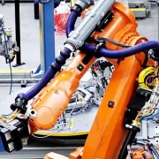
Robot Cable Assemblies Face More Than Simple Bending
Robot applications can be even more demanding than linear drag chains.
A robotic arm may subject the harness to combinations of:
- Bending
- Torsion
- Rotation
- Acceleration
- Vibration
A cable suitable for repeated two-dimensional bending may not automatically be suitable for robot torsion.
Some robot cable specifications therefore define separate torsion angles, cycle counts, and bending requirements.
LAPP, for example, publishes industrial communication cables specifically tested for repeated torsional motion, demonstrating that torsion and simple flexing should be treated as different mechanical load cases.
Bend Radius in Robot Body Harness Design
For robot body wiring, the harness is often routed through or along multiple moving joints.
Engineers should evaluate:
- Maximum arm extension
- Minimum arm position
- Joint rotation
- Cable twisting
- Cable slack
- Potential pinch points
- Cable-to-frame contact
- Strain relief at connectors
- Repeated bend locations
The harness should not be evaluated only in the robot’s neutral position.
It needs to be reviewed across the complete motion envelope.
Why Servo Cable Assemblies Need Mechanical Design Review
Servo systems frequently combine:
- Motor power
- Brake circuits
- Encoder signals
- Feedback signals
These may be integrated into one cable assembly or separated into multiple cables.
FPIC’s servo cable assembly portfolio supports customized cable types, lengths, and connector combinations, including SCSI, DB/HDB, MIL-type, M-series and other industrial interfaces.
In moving servo applications, cable design should consider both electrical and mechanical performance.
Key questions include:
- Is the cable rated for continuous flexing?
- What is the manufacturer’s dynamic bend radius?
- Does the cable contain shields?
- Will it operate in a drag chain?
- What are the travel length and acceleration?
- Is torsion involved?
- Where is the connector mounted?
These questions should be resolved during engineering review rather than after the cable assembly has already been produced.
Cable Construction Influences Bend Performance
Bend radius cannot be evaluated from cable diameter alone.
Two cables with the same outer diameter may behave very differently.
Conductor Stranding
Fine-stranded conductors generally tolerate repeated flexing better than coarse or solid conductors.
HELUKABEL identifies fine and extra-fine stranded copper constructions in its drag-chain and robot cable products.
Core Lay
The way individual conductors are twisted together affects flexibility and internal movement.
Optimized lay lengths can help distribute mechanical stress.
Insulation Material
Insulation must remain flexible through the operating temperature range.
A material that becomes stiff at low temperature may require different design considerations.
Shielding
Braided and foil structures react differently under repeated bending and torsional movement.
Jacket Material
The outer sheath may need resistance to:
- Abrasion
- Oil
- Coolants
- Moisture
- Chemicals
- Low temperatures
Cable selection should therefore consider the complete operating environment rather than only bend radius.
Temperature Can Change Cable Flexibility
Cable flexibility is temperature-dependent.
At lower temperatures, some polymers become stiffer.
At elevated temperatures, material properties may also change.
This means a cable that bends easily during room-temperature assembly may behave differently inside:
- Cold warehouses
- Outdoor equipment
- High-temperature machinery
- Refrigeration equipment
Dynamic bend-radius specifications should therefore be reviewed together with the allowable flexible operating temperature.
Cable datasheets commonly list separate temperature ranges for fixed and flexible operation. HELUKABEL’s drag-chain cable documentation, for example, distinguishes these operating conditions alongside the corresponding bending requirements.
Bend Radius Is Also an Installation-Space Requirement
One of the most practical design mistakes occurs when the electrical design is completed before the physical cable route is checked.
A designer may select:
- Correct connector
- Correct cable
- Correct pinout
but later discover that the cabinet does not provide enough space for the required cable bend.
This often leads to installers forcing the cable into the available space.
The problem is then no longer the cable specification.
It is the mechanical layout.
Required Installation Space
A designer should consider:
- Connector body length
- Strain-relief length
- Required straight exit
- Minimum cable bend radius
- Cable diameter
- Adjacent components
- Door movement
- Maintenance clearance
In compact machinery, these dimensions can influence connector orientation and equipment layout.
Sample Validation Should Include the Real Installation Geometry
Prototype validation should not be limited to checking whether the cable assembly matches the drawing.
The sample should ideally be evaluated in the actual equipment or a representative installation fixture.
What Should Be Checked?
Connector Installation
Confirm:
- Correct orientation
- Mating accessibility
- Locking operation
Cable Routing
Confirm:
- Bend radius
- Cable path
- Clearance from sharp edges
- No excessive tension
Strain Relief
Confirm:
- Cable is properly supported
- Force is not transferred directly into the termination
Motion
For dynamic applications:
- Move the machine through its full travel
- Observe cable behavior
- Check for twisting
- Check for pulling
- Identify concentrated bend locations
Serviceability
Confirm that technicians can:
- Disconnect the cable
- Replace the assembly
- Access adjacent components
This is why early sample validation can prevent expensive mechanical changes after mass production begins.
How Bend Testing Supports Design Validation
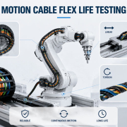
For dynamic applications, physical testing helps verify whether the cable construction can tolerate the required movement.
A bending test may define:
- Bend radius
- Travel distance
- Speed
- Number of cycles
- Load
- Temperature
- Cable orientation
Possible evaluation criteria include:
- Electrical continuity
- Conductor resistance
- Jacket damage
- Insulation damage
- Shield performance
- Mechanical failure
HELUKABEL describes laboratory bending tests using controlled loads and bending radii to evaluate cable mechanical strength, including repeated bending methods.
The test conditions should represent the customer’s actual application rather than relying on an arbitrary cycle count.
What Information Should Be Defined Before Designing a Moving Harness?
For robotic, drag-chain, or servo applications, customers should ideally provide:
| Design Input | Information Needed |
| Application | Robot, servo axis, drag chain, machine tool, sensor |
| Cable type | Power, signal, data, hybrid, shielded |
| Outer diameter | Actual selected cable diameter |
| Movement | Fixed, occasional flex, continuous flex, torsion |
| Minimum radius | Cable manufacturer specification |
| Travel | Total moving distance |
| Speed | Operating movement speed |
| Acceleration | Maximum acceleration |
| Cycles | Expected movement frequency / service life |
| Temperature | Fixed and moving operating range |
| Environment | Oil, coolant, abrasion, moisture |
| Connector | Type and exit orientation |
| Installation | Drag chain, robot body, free routing |
| Available space | Physical routing envelope |
Providing these parameters during RFQ or prototype development allows the wire harness manufacturer to evaluate the complete mechanical design rather than simply quoting a cable length.
Common Bend-Radius Design Mistakes
Mistake 1: Using One Bend-Radius Rule for Every Cable
Different constructions have different limits.
Better approach: Follow the actual cable datasheet.
Mistake 2: Using the Fixed Radius for a Moving Cable
The static and dynamic ratings may be significantly different.
Better approach: Define the real movement profile during design.
Mistake 3: Selecting a Flexible Cable for a Continuous-Flex Application
Flexibility by hand does not prove drag-chain capability.
Better approach: Specify a cable qualified for the actual dynamic application.
Mistake 4: Bending Immediately After the Connector
This transfers stress into the termination.
Better approach: Provide strain relief and controlled routing after the connector exit.
Mistake 5: Ignoring the Full Robot Motion Envelope
A harness may look correct when the robot is stationary but become overstretched at maximum reach.
Better approach: Verify all critical positions during prototype testing.
Mistake 6: Designing the Cable After the Mechanical Layout Is Frozen
The available space may not accommodate the required radius.
Better approach: Include cable routing during equipment mechanical design.
Bend Radius vs. Other Mechanical Cable Requirements
Bend radius is important, but it is only one part of mechanical harness design.
| Requirement | Primary Concern |
| Bend radius | Excessive curvature |
| Flex life | Repeated bending cycles |
| Torsion | Rotational twisting |
| Strain relief | Load at the termination |
| Abrasion resistance | Surface wear |
| Tensile load | Cable pulling |
| Vibration resistance | Repeated mechanical excitation |
| Routing clearance | Contact with equipment |
| Temperature | Material flexibility and aging |
FPIC Support for Industrial and Moving Cable Assemblies
FPIC provides customized industrial wire harness and cable assembly solutions for machinery, automation equipment, servo systems, and other industrial applications.
FPIC’s product documentation includes industrial wire harnesses and customized servo cable assemblies with configurable cable types, lengths, and connector combinations.
For suitable projects, engineering review can consider:
- Cable specification
- Connector selection
- Cable length
- Connector orientation
- Routing requirements
- Strain relief
- Shield termination
- Production feasibility
- Testing requirements
FPIC’s existing wire harness manufacturing documentation also shows automated wire cutting, terminal crimping, automatic housing insertion, visual inspection, alignment checks, and electrical testing within its production capability.
Its quality documentation states that incoming cables and components are checked and that cable and harness manufacturing is managed under established quality systems and ERP/MES production controls.
Why Prototype Review Is Important for Custom Harnesses
A CAD drawing can define dimensions.
It cannot always reveal how a cable behaves during actual installation.
For industrial equipment, a prototype can help answer:
- Does the connector fit the real installation angle?
- Is there enough clearance for the cable bend?
- Does the cable rub against a frame?
- Is the cable pulled when the machine moves?
- Is strain relief effective?
- Can maintenance personnel access the connector?
- Does the selected cable remain flexible under real conditions?
This feedback can then be used to optimize:
- Cable length
- Connector orientation
- Routing
- Clamping
- Protective sleeves
- Strain-relief structure
before mass-production tooling or fixtures are finalized.
How to Evaluate a Wire Harness Supplier for Dynamic Applications
When sourcing a robotic or continuous-flex cable assembly, buyers should ask more than:
“Can you make this cable?”
Useful questions include:
- Do you review the cable manufacturer’s dynamic bend-radius specification?
- Can you evaluate connector orientation and available installation space?
- Do you distinguish fixed, flexible, drag-chain, and torsional applications?
- Can you support prototype fit checks?
- Can the assembly be tested for repeated bending when required?
- How are connector terminations protected from cable movement?
- Can electrical testing be performed before and after mechanical validation?
- Can cable, connector, and production requirements be customized together?
These questions help identify whether the supplier is treating the harness as an engineered system rather than only an assembled cable.
Conclusion
Cable bend radius is a fundamental design parameter in industrial wire harnesses.
When a cable is bent too tightly, the resulting stress can affect:
- Conductors
- Insulation
- Shielding
- Outer jackets
- Connector terminations
The risk becomes significantly greater in:
- Robots
- Servo systems
- Drag chains
- Repeated-motion machinery
A reliable design should therefore consider:
Cable Construction → Bend Radius → Connector Exit → Strain Relief → Motion Profile → Installation Space → Prototype Validation
Most importantly, engineers should not apply one generic bend-radius multiplier to every project.
The correct minimum radius must come from the actual cable specification and should reflect whether the cable is used in a fixed, flexible, drag-chain, or torsional application.
For custom industrial wire harnesses, reviewing these mechanical requirements during the prototype stage can prevent routing problems, premature cable fatigue, connector stress, and costly equipment redesign later in the project.
FAQ
What is the minimum bend radius of a cable?
The minimum bend radius is the smallest radius at which a specific cable can be bent without exceeding its intended mechanical limits. The value should be taken from the cable manufacturer’s datasheet.
How is cable bend radius calculated?
It is commonly specified as a multiple of cable outer diameter. If a datasheet specifies a factor of k, the minimum radius is calculated as cable outer diameter × k.
Is the bend radius the same for fixed and moving cables?
No. Dynamic applications usually have different and often larger minimum bending-radius requirements because the cable experiences repeated mechanical stress.
What happens if a cable is bent below its minimum radius?
Possible effects include conductor fatigue, insulation deformation or cracking, shield damage, jacket deformation, increased stress at the connector, and reduced service life.
Is a flexible cable suitable for a drag chain?
Not necessarily. A cable must be specifically designed and qualified for continuous-flex or drag-chain use when the application requires repeated motion.
Why should the cable not bend immediately after a connector?
An immediate bend can transfer mechanical stress into the crimp, solder joint, shield termination, gland, or connector housing.
What is the role of strain relief?
Strain relief reduces tensile, bending, and torsional loads transferred from the cable into the electrical termination.
How should robot cable assemblies be validated?
The harness should be evaluated across the robot’s actual motion envelope, including maximum extension, joint rotation, bend locations, torsion, routing clearance, and connector strain.
Should bend radius be checked during prototyping?
Yes. Prototype installation is one of the best opportunities to verify whether the theoretical cable route is practical inside the real equipment.
Design Your Industrial Cable Assembly for the Real Application
FPIC supports customized industrial wire harness and cable assembly projects from engineering review and prototype evaluation through wire processing, connector assembly, electrical testing, and mass production.
For moving or space-constrained applications, provide:
- Harness drawing
- Cable specification
- Connector requirements
- Equipment layout
- Available routing space
- Motion profile
- Expected cycle requirement
Our team can evaluate the assembly requirements before production. Email: info@sz-fpi.com
Resources
- HELUKABEL — The Meaning of Bending Radius for Cables and Drag Chains
Explains minimum bend radius, differences between fixed and dynamic applications, and the importance of following cable-specific manufacturer specifications. - HELUKABEL — MULTISPEED 500-C-PVC Drag Chain Cable
Provides a real industrial example showing different minimum bend-radius specifications for fixed and flexible applications. - LAPP — Technical Assembly Guidelines for Industrial Cables
Explains that fixed, flexible, drag-chain, and torsional applications require different cable constructions and emphasizes observing minimum bend radius in cable carriers. - HELUKABEL — Cable Bending Test Guidance
Discusses laboratory bending tests used to evaluate cable mechanical strength under different loads and bending radii.