Wire Harness Design for Servo Systems: Reducing Noise, Crosstalk and Downtime
Servo systems are the backbone of modern industrial automation. They are widely used in CNC machines, robotics, packaging equipment, and precision motion control systems. However, as system performance increases, so do the challenges associated with electrical noise, signal interference, and unexpected downtime.
A poorly designed wire harness in a servo system can lead to unstable motion, encoder errors, communication loss, and even complete machine shutdowns.
This article explains how proper wire harness design can significantly reduce noise, crosstalk, and downtime in servo-driven applications.
Why Servo Systems Are Sensitive to Wiring Design
Servo systems rely on high-speed feedback loops between:
- servo drives
- servo motors
- encoders
- controllers (PLC or motion controller)
These signals are highly sensitive to:
- electromagnetic interference (EMI)
- voltage fluctuations
- grounding instability
- cable coupling effects
Even small disturbances in signal integrity can lead to:
- position errors
- unstable torque output
- unexpected motion behavior
- system alarms or shutdowns
In many cases, the root cause is not the servo system itself—but the wiring architecture.
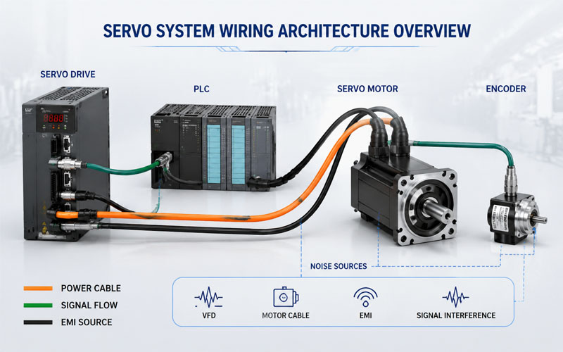
Understanding Noise Sources in Servo Applications
Electrical noise in servo systems typically comes from:
- servo drive switching signals
- motor power cables
- nearby high-voltage equipment
- variable frequency drives (VFDs)
- poor grounding design
These sources generate both conducted and radiated EMI.
Without proper cable design, noise can couple into:
- encoder feedback lines
- communication cables (EtherCAT, CANopen, etc.)
- sensor signals
This results in unstable system performance.
Cable Crosstalk: A Hidden Performance Killer
Crosstalk occurs when signals in adjacent conductors interfere with each other.
In servo systems, this is especially critical because:
- encoder signals are low voltage and high frequency
- power cables carry high current switching noise
- cables are often bundled in tight spaces
Common causes of crosstalk include:
- insufficient shielding
- long parallel cable runs
- poor cable separation
- improper grounding
- high-density harness bundling
Design impact:
Crosstalk can lead to:
- incorrect position feedback
- jitter in motion control
- intermittent communication errors
- reduced system accuracy
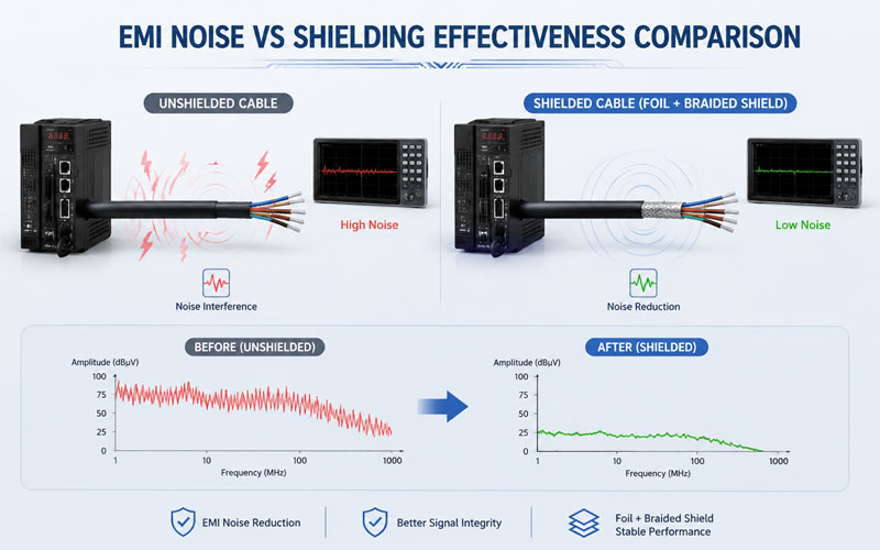
Shielding Design for Servo Cable Assemblies
Proper shielding is one of the most effective ways to reduce noise and crosstalk.
Foil Shielding
Best for:
- high-frequency noise protection
- data and communication lines
Advantages:
- 100% coverage
- lightweight
- cost-effective
Limitations:
- lower mechanical durability
Braided Shielding
Best for:
- motor power cables
- harsh industrial environments
Advantages:
- strong mechanical protection
- good low-frequency noise suppression
- better grounding path
Combined Shielding
Used in high-performance servo systems:
- foil + braid combination
- broad-frequency EMI protection
- improved system stability
Grounding Strategy: The Most Overlooked Factor
Even the best shielded cable will fail without proper grounding.
Recommended practices:
- single-point grounding for signal integrity
- 360° shield termination at connector end
- low-impedance grounding paths
- avoid long ground loops
Common mistakes:
- floating shields
- pigtail grounding (high impedance)
- inconsistent grounding across system
Poor grounding is one of the main causes of servo instability.
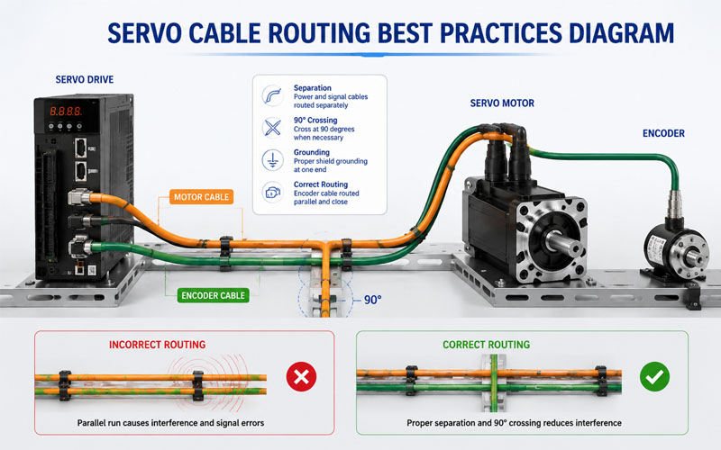
Cable Routing and Separation Strategy
Proper routing is essential to reduce interference.
Key principles:
✔ Separate power and signal cables
✔ Avoid parallel long-distance routing
✔ Cross cables at 90° when necessary
✔ Keep encoder cables away from motor cables
✔ Minimize loop areas
Why it matters:
Even well-shielded cables can suffer interference if routing is incorrect.
Connector Design and Interface Integrity
Servo system performance is highly dependent on connector reliability.
Key considerations:
- low contact resistance
- secure locking mechanisms
- EMI-shielded connector housings
- vibration-resistant design
- proper strain relief integration
Connector instability can introduce:
- intermittent signal loss
- increased noise sensitivity
- unexpected system downtime
Strain Relief and Mechanical Stability
Servo systems operate under continuous motion and vibration.
Without proper strain relief:
- conductor fatigue increases
- shield continuity may break
- connectors may loosen over time
Best practices include:
- molded strain relief boots
- clamp-based retention
- proper bend radius control
- avoiding stress at connector exits
Downtime Reduction Through Cable Design
In industrial automation, downtime is often more costly than component replacement.
A well-designed servo wire harness helps reduce downtime by:
- improving signal stability
- reducing electrical noise sensitivity
- increasing mechanical durability
- minimizing connector failures
- extending maintenance intervals
Validation for Servo Cable Assemblies
Testing is essential to ensure reliability.
Key validation tests include:
- EMI/EMC testing
- flex life testing
- torsion testing (for motion systems)
- continuity and resistance testing
- vibration testing
- temperature cycling
Validation ensures real-world performance matches design expectations.
How FPIC Supports Servo System Cable Design
Servo applications require a combination of electrical precision and mechanical durability.
FPIC provides custom wire harness and connector solutions for servo systems used in industrial automation, robotics, and motion control applications. Our engineering support includes shielding design optimization, routing recommendations, strain relief design, and production validation to improve system reliability and reduce downtime.
Final Thoughts
Servo system performance depends heavily on wire harness design. Noise, crosstalk, and downtime are often not caused by the servo components themselves, but by inadequate shielding, poor routing, and weak mechanical design.
By optimizing shielding, grounding, cable layout, and strain relief, engineers can significantly improve system stability and long-term reliability.
FAQ
What causes noise in servo systems?
Noise is mainly caused by EMI from servo drives, motors, VFDs, and poor grounding or shielding design.
What is crosstalk in servo cables?
Crosstalk is unwanted signal interference between adjacent conductors, often caused by poor shielding or tight cable bundling.
How can downtime in servo systems be reduced?
Downtime can be reduced by improving cable shielding, routing, grounding, and mechanical strain relief design.
Do servo motor cables need shielding?
Yes, shielding is essential to reduce EMI and ensure stable feedback and control signals.
What is the most common wiring mistake in servo systems?
Incorrect grounding and poor separation between power and signal cables are the most common issues.
Need a Reliable Servo Cable Solution?
If your servo system is affected by noise, instability, or unexpected downtime, the wire harness design may be the root cause. FPIC provides custom servo cable assemblies designed for high-performance motion control applications.
Contact FPIC to optimize your servo wiring system today.
Resources
- LAPP – Servo Motor Cable Technology: https://www.lapp.com
Explains design principles for servo cables, shielding, and EMC performance. - Siemens – Motion Control Wiring Guidelines: https://www.siemens.com
Provides best practices for servo system wiring, grounding, and noise reduction. - Belden – Industrial Ethernet and Servo Cabling: https://www.belden.com
Covers shielding, crosstalk reduction, and industrial communication stability. - IEC 61800-3 Standard – Adjustable Speed Drives EMC: https://www.iec.ch
International standard for electromagnetic compatibility in drive systems. - IEEE Xplore – Servo System Noise and EMC Studies: https://ieeexplore.ieee.org
Research papers on noise reduction and wiring design in motion control systems.


