Energy Storage Wire Harness Design: Busbar Interface, Temperature Rise and Safety Margin
Energy storage systems (ESS) are rapidly becoming a critical part of modern power infrastructure. From residential battery storage and commercial microgrids to utility-scale battery energy storage systems (BESS), reliable electrical interconnection is essential for safe and efficient operation.
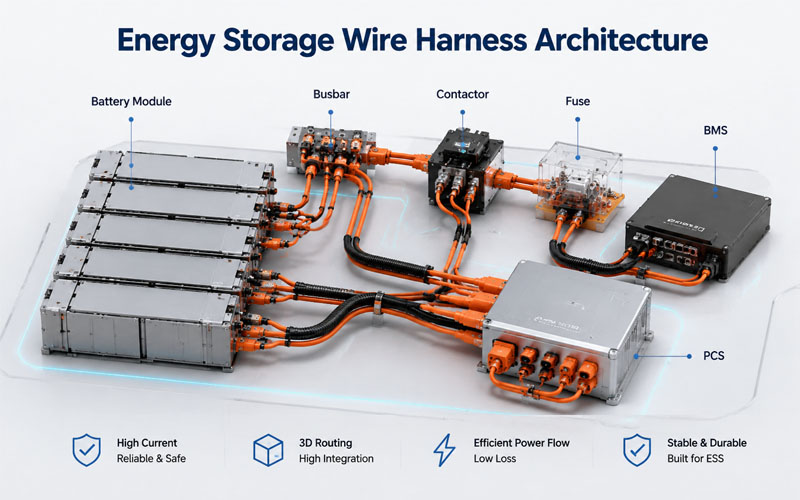
While battery cells and battery management systems (BMS) often receive the most attention, the wire harness is equally important. High-current cable assemblies connect battery modules, busbars, contactors, fuses, and power conversion equipment. A poorly designed harness can increase resistance, generate excessive heat, reduce system efficiency, and even create safety risks.
This article explores three key design considerations for energy storage wire harnesses: busbar interfaces, temperature rise, and safety margins.
Why Wire Harness Design Matters in Energy Storage Systems
Unlike conventional industrial equipment, energy storage systems continuously transfer large amounts of electrical power.
Typical ESS applications involve:
- High continuous current
- Frequent charge and discharge cycles
- Elevated ambient temperatures
- Compact equipment layouts
- Long service life requirements
These operating conditions place significant demands on cable assemblies and electrical connections.
A small increase in contact resistance can generate substantial heat under high current, accelerating insulation aging and reducing connector life.
Designing Reliable Busbar Interfaces
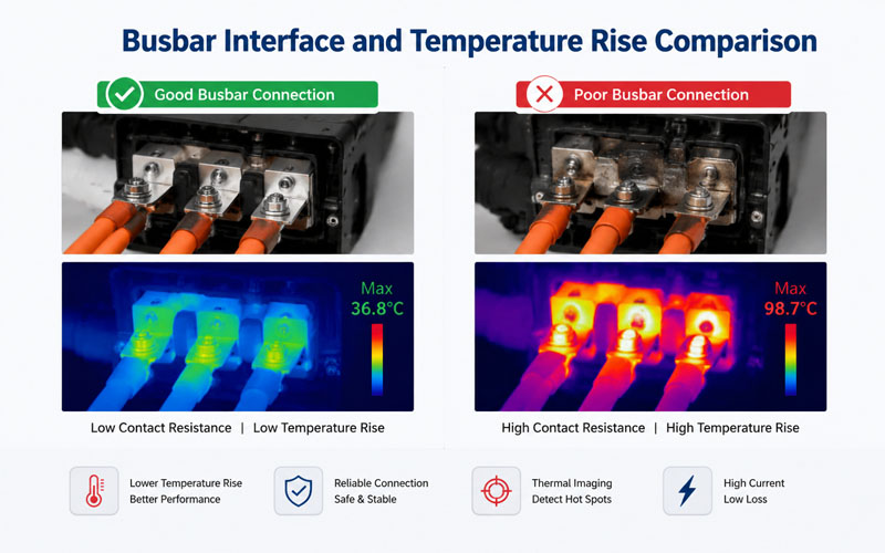
The interface between the wire harness terminal and the busbar is one of the most critical electrical connections within a battery system.
Poor interface design can result in:
- increased contact resistance
- localized heating
- voltage loss
- connector loosening
- reduced system efficiency
Selecting the Right Terminal
Terminal selection should consider:
- rated current
- conductor size
- plating material
- crimp quality
- mechanical strength
Tin-plated copper terminals are widely used, while silver plating may be selected for higher current applications where lower contact resistance is required.
Optimizing Contact Pressure
Stable contact pressure ensures consistent electrical performance.
Engineers should evaluate:
- bolt torque
- terminal thickness
- washer design
- vibration resistance
Insufficient clamping force increases resistance, while excessive torque may damage terminals or busbars.
Minimizing Contact Resistance
Contact resistance is often measured in micro-ohms, but even small increases can significantly affect system performance.
Factors influencing contact resistance include:
- terminal surface finish
- oxidation
- contamination
- insufficient torque
- repeated connection cycles
Reducing resistance helps improve:
- charging efficiency
- discharge efficiency
- thermal performance
- connector lifespan
Regular inspection and proper assembly procedures are equally important as component selection.
Understanding Temperature Rise
Temperature rise is one of the most important design considerations for high-current wire harnesses.
Heat is generated by:
- conductor resistance
- contact resistance
- ambient temperature
- cable bundling
- restricted airflow
Even when operating below the cable’s rated current, poor installation conditions can significantly increase conductor temperature.
Why Temperature Rise Matters
Excessive temperatures can lead to:
- insulation aging
- connector deformation
- increased resistance
- reduced current capacity
- shortened service life
Thermal management should therefore be considered during both electrical and mechanical design.
Cable Sizing Beyond Current Ratings
Many designers select cable size solely according to current carrying capacity.
However, proper sizing should also account for:
- installation method
- ambient temperature
- grouping factors
- voltage drop
- continuous duty cycle
For example, multiple high-current cables installed within confined battery enclosures often require derating.
Ignoring derating factors may result in unexpected overheating.
Thermal Management Inside Battery Packs
Modern battery systems are becoming increasingly compact, reducing available space for heat dissipation.
Good thermal design includes:
- adequate cable spacing
- optimized routing
- ventilation pathways
- separation from heat sources
High-current cables should avoid close proximity to:
- power electronics
- contactors
- cooling system exhaust
- battery module hot spots
Reducing localized heat accumulation improves overall system reliability.
Maintaining Appropriate Safety Margins
Electrical systems should not be designed to operate continuously at their absolute limits.
Safety margins help compensate for:
- manufacturing tolerances
- aging
- environmental changes
- load fluctuations
- unexpected overloads
Typical design reviews evaluate:
- conductor temperature margin
- connector current margin
- voltage margin
- insulation margin
The exact safety margin depends on application requirements, operating conditions, and applicable industry standards.
Mechanical Protection for High-Current Harnesses
Electrical performance is only part of the design challenge.
Wire harnesses must also withstand:
- vibration
- installation stress
- transportation
- maintenance activities
Protection methods include:
- abrasion-resistant sleeves
- corrugated conduit
- cable clamps
- strain relief
- insulated busbar covers
Mechanical durability directly affects long-term electrical reliability.
Validation and Testing
Before production, energy storage harnesses should undergo comprehensive validation.
Typical tests include:
- continuity testing
- insulation resistance testing
- temperature rise testing
- current cycling
- vibration testing
- pull force testing
- dielectric withstand testing (Hi-Pot)
- thermal cycling
Validation should replicate actual operating conditions as closely as possible.
Industry Standards to Consider
Energy storage wire harness development often references international standards such as:
- IEC 62933 (Electrical Energy Storage Systems)
- UL 9540 (Energy Storage Systems and Equipment)
- UL 1973 (Batteries for Stationary Applications)
- IEC 61439 (Low-Voltage Switchgear Assemblies)
Depending on the application, additional customer-specific validation requirements may also apply.
How FPIC Supports Energy Storage Cable Assembly Projects
Energy storage applications require reliable high-current interconnections that combine electrical performance with mechanical durability.
FPIC provides custom energy storage wire harnesses and high-current cable assemblies for battery energy storage systems, power distribution units, and battery packs. Our engineering team supports customers with conductor selection, terminal crimp optimization, busbar interface design, connector integration, and production validation to improve long-term system reliability.
Final Thoughts
As energy storage systems continue to grow in capacity and power density, wire harness design plays an increasingly important role in system safety and efficiency.
Reliable busbar interfaces, controlled temperature rise, and appropriate safety margins help reduce energy loss, improve equipment reliability, and extend service life.
By considering electrical, thermal, and mechanical factors together, engineers can build energy storage systems that deliver consistent performance under demanding operating conditions.
FAQ
Why is contact resistance important in energy storage wire harnesses?
Even small increases in contact resistance can generate significant heat under high current, reducing efficiency and shortening connector life.
How can temperature rise be reduced in battery cable assemblies?
Proper cable sizing, optimized routing, improved ventilation, and secure busbar connections all help minimize temperature rise.
Why shouldn’t cable sizing be based only on current rating?
Ambient temperature, cable bundling, installation method, and duty cycle all influence the actual current carrying capacity.
What is the purpose of a safety margin in ESS wiring design?
Safety margins compensate for aging, manufacturing variation, overload conditions, and environmental changes to improve long-term reliability.
Which tests are recommended for energy storage wire harnesses?
Common tests include continuity, insulation resistance, temperature rise, current cycling, vibration, Hi-Pot, and thermal cycling tests.
Developing a High-Current Wire Harness for Energy Storage?
Reliable battery systems depend on more than high-quality cells. FPIC provides custom energy storage wire harnesses and high-current cable assemblies engineered for battery packs, ESS cabinets, and power distribution systems.
Contact FPIC today to discuss your energy storage project requirements.
Resources
- IEC 62933 – Electrical Energy Storage (EES) Systems: Provides international standards for the planning, installation, and safety of electrical energy storage systems.
- UL 9540 – Energy Storage Systems and Equipment: Covers safety requirements for complete energy storage systems, including electrical interconnections and system integration.
- UL 1973 – Batteries for Stationary Applications: Defines safety requirements for stationary battery systems used in energy storage applications.
- TE Connectivity – Energy Storage Connectivity Solutions: Discusses high-current connectors, busbar interfaces, and cable assemblies for battery energy storage systems.
- Phoenix Contact – Connection Technology for Battery Energy Storage Systems: Explains connection technologies, thermal considerations, and high-current interfaces used in modern ESS installations.
