How to Select Wires, Terminals and Connectors for Custom Harness Design
A custom wire harness is more than a group of wires assembled with connectors.
It is an integrated electrical and mechanical system in which wires, terminals, connectors, seals, protection materials, and routing features must work together.
Selecting the wrong component can create problems that may not appear during initial assembly but emerge later in the field.
Examples include:
- Excessive voltage drop
- Overheating
- Contact resistance increase
- Terminal pull-out
- Connector damage
- Water or dust ingress
- Cable fatigue
- Intermittent electrical failures
For this reason, wire, terminal, and connector selection should begin with the actual application requirements rather than simply choosing components based on availability or nominal current rating.
A systematic selection process helps engineers balance:
Electrical Performance + Mechanical Reliability + Environmental Resistance + Manufacturability + Cost
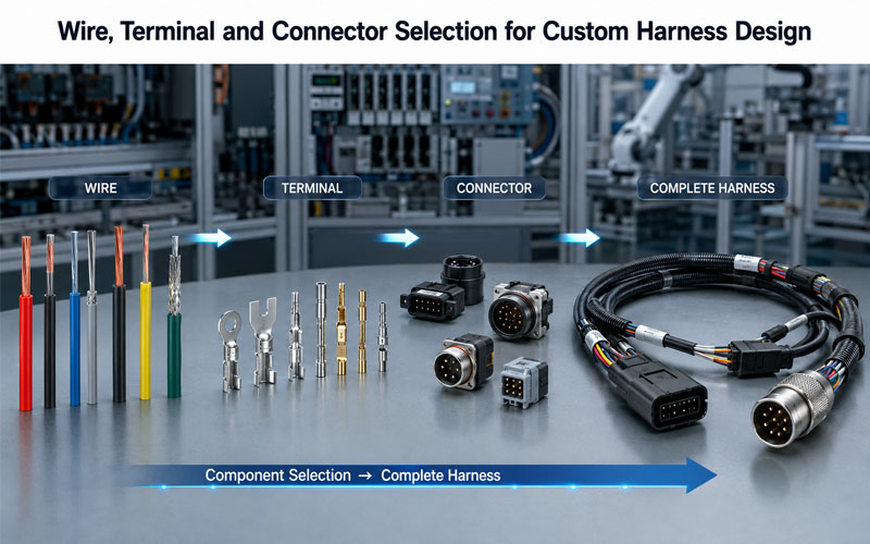
Start With the Application Requirements
Before selecting individual components, define the operating conditions of the harness.
Important parameters include:
- Voltage
- Continuous current
- Peak current
- Signal type
- Operating temperature
- Ambient environment
- Vibration
- Shock
- Flexing
- Mating cycles
- Required IP protection
- Available installation space
- Expected service life
A harness used inside a stationary control cabinet may require very different components from one installed on a moving robotic arm.
Therefore:
Application → Requirements → Component Selection
should be the basic design sequence.
1.How to Select the Wire
The wire is the primary electrical path in the harness.
Wire selection should consider more than conductor size.
Key factors include:
- Conductor material
- Conductor cross-sectional area
- Voltage rating
- Current capacity
- Insulation material
- Temperature rating
- Flexibility
- Shielding
- Chemical resistance
- Abrasion resistance
2.Select Wire Gauge Based on Current
Current capacity is one of the first considerations.
A conductor that is too small may experience excessive:
- Temperature rise
- Voltage drop
- Electrical resistance
- Insulation stress
A larger conductor can reduce these issues but may increase:
- Harness diameter
- Weight
- Cost
- Routing difficulty
- Connector terminal size
The objective is to select a conductor that meets the actual electrical requirements without unnecessary oversizing.
3.Consider Voltage Drop
Current capacity alone is not enough.
For longer harnesses, voltage drop can become significant.
Voltage drop depends on factors such as:
- Conductor resistance
- Wire length
- Current
- Conductor size
- Temperature
A harness for sensitive electronics may require tighter voltage-drop control than a short power connection.
Engineers should therefore evaluate the complete electrical path:
Power Source → Wire → Terminal → Connector → Load
4.Consider Temperature Rating
Wire insulation must remain suitable for the expected operating temperature.
Potential temperature sources include:
- Ambient temperature
- Nearby heat sources
- Current-generated heating
- Engine compartments
- Power electronics
- Enclosures with limited ventilation
Common insulation materials include:
- PVC
- XLPE
- TPE
- TPU
- PTFE
- Silicone
Material selection should be based on actual temperature and environmental requirements rather than material name alone.
5.Select Wire Based on Flexibility
Static and dynamic applications require different cable characteristics.
Static Applications
Typical requirements may focus on:
- Cost
- Temperature
- Voltage
- Chemical resistance
- Installation space
Dynamic Applications
Additional requirements include:
- Flexibility
- Torsion resistance
- Repeated bending
- Flex life
- Bend radius
Robotic arms, drag chains, servo systems, and moving machinery require particularly careful cable selection.
6.Consider Shielding Requirements
For signal and communication harnesses, electromagnetic interference can affect system performance.
Shielding may be required for:
- Industrial Ethernet
- CAN
- Sensor signals
- Servo systems
- Data communication
- High-frequency signals
Possible shielding structures include:
- Foil shield
- Braided shield
- Combination shielding
However, selecting a shielded cable is only one part of EMC design.
The shield termination, connector, grounding strategy, and harness routing must also be considered.
7.How to Select Terminals
The terminal creates the electrical and mechanical interface between the wire and connector.
Terminal selection should consider:
- Wire size
- Current rating
- Contact force
- Material
- Plating
- Crimp geometry
- Retention requirements
- Mating cycles
- Environmental conditions
The terminal must be compatible with both the selected wire and connector housing.
8.Match Terminal Size to Wire Size
A terminal should be designed for the conductor size range being used.
An incorrect combination can cause:
Undersized Terminal
Potential issues:
- Poor conductor fit
- Excessive resistance
- Overheating
- Weak mechanical retention
Oversized Terminal
Potential issues:
- Poor crimp formation
- Insufficient mechanical grip
- Inconsistent electrical performance
Correct terminal-to-wire matching is therefore essential.
9.Crimp Quality Matters
A terminal is only as reliable as its termination.
The crimp must provide:
Electrical Connection + Mechanical Retention
Important parameters include:
- Crimp height
- Crimp width
- Conductor insertion
- Insulation support
- Terminal deformation
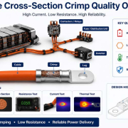
For high-volume manufacturing, controlled crimping processes help improve consistency.
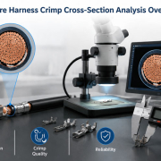
Crimp validation may include:
- Pull-force testing
- Cross-section analysis
- Visual inspection
- Crimp-height measurement
10.Terminal Plating Selection
Terminal plating affects contact performance and durability.
Common plating options include:
Tin Plating
Often used for cost-effective general applications.
Gold Plating
Can provide excellent corrosion resistance and stable contact performance, particularly for low-level signals and demanding environments.
Silver Plating
Can be suitable for certain high-current or high-temperature applications depending on the design.
The correct plating depends on:
- Current
- Voltage
- Signal level
- Mating cycles
- Temperature
- Corrosive environment
- Cost target
11.How to Select the Connector
Connector selection should consider the complete application rather than simply the number of pins.
Important parameters include:
- Number of circuits
- Current
- Voltage
- Contact pitch
- Connector size
- Mating direction
- Locking method
- Mating cycles
- IP rating
- Temperature
- Vibration
- Mounting method
A connector suitable for a consumer electronic device may not be appropriate for an automotive or industrial application.
12.Match Connector Current Rating to the Complete System
Connector current capability depends on more than the connector’s nominal rating.
Engineers should consider:
- Terminal material
- Contact resistance
- Wire gauge
- Number of loaded circuits
- Ambient temperature
- Connector size
- Heat dissipation
When several high-current circuits are packed into a small housing, thermal interaction between adjacent terminals can affect the actual operating condition.
Therefore, the complete connector system should be evaluated rather than relying on a single catalog value.
13.Select the Correct Connector Pitch
Contact pitch affects:
- Connector size
- Contact density
- Electrical clearance
- Manufacturing precision
- Mating alignment
Fine-pitch connectors can reduce package size but typically require tighter dimensional control.
For high-density applications, engineers should evaluate whether the required pitch provides sufficient:
- Insulation
- Mechanical strength
- Terminal spacing
- Manufacturing tolerance
14.Consider Connector Locking Mechanisms
A connector used in a high-vibration environment should provide reliable mechanical retention.
Possible mechanisms include:
- Primary locks
- Secondary locks
- CPA structures
- Threaded coupling
- Push-pull locking
- Latching systems
The choice depends on:
- Vibration
- Service requirements
- Mating frequency
- Installation space
- Connector size
15.Environmental Protection
Environmental conditions can significantly affect component selection.
Consider exposure to:
- Water
- Dust
- Oil
- Chemicals
- Salt spray
- UV
- Temperature cycling
For outdoor or industrial applications, an appropriate IP-rated connector may be required.
However, the connector rating alone does not guarantee complete harness protection.
The cable, seals, backshells, overmolding, and interfaces must all work together.
16.Connector and Terminal Material Compatibility
Materials should be considered as a system.
For example:
Wire → Terminal → Connector Housing → Seal
Potential material interactions can affect:
- Corrosion
- Thermal performance
- Mechanical stability
- Chemical resistance
Material compatibility becomes especially important in harsh environments.
17.Consider Strain Relief
Connector selection should include cable-exit requirements.
If the cable leaves the connector without adequate support, external forces can reach the terminal or crimp.
Possible solutions include:
- Overmolding
- Backshells
- Cable clamps
- Grommets
- Protective boots
Strain relief is particularly important for moving harnesses.
18.Consider Bend Radius
Wire and connector selection must support the required routing path.
A cable with a large minimum bend radius may not be suitable for a compact installation.
Conversely, a cable forced into an excessively tight bend may experience:
- Conductor fatigue
- Insulation damage
- Shield deformation
- Reduced flex life
The harness design should therefore consider:
Cable Construction + Bend Radius + Routing Space + Movement
19.Design for Manufacturability
A technically suitable component may still be a poor choice if it is difficult to manufacture consistently.
During DFM review, engineers should evaluate:
- Terminal availability
- Crimp tooling
- Automatic assembly compatibility
- Connector insertion process
- Wire stripping requirements
- Inspection methods
- Packaging
- Supply stability
A component that cannot be reliably manufactured at production volume may create significant downstream costs.
20.Standard vs Custom Components
OEM harness projects often require a decision between standard and customized components.
Standard Components
Advantages:
- Established supply chain
- Existing tooling
- Faster development
- Lower initial cost
Custom Components
Advantages:
- Optimized dimensions
- Application-specific performance
- Integrated functions
- Greater design flexibility
The correct choice depends on production volume, performance requirements, development timeline, and total cost.
Component Selection Matrix
A simple engineering matrix can help compare candidate components.
| Requirement | Wire | Terminal | Connector |
|---|---|---|---|
| Current | Gauge / conductor size | Contact capacity | System rating |
| Voltage | Insulation rating | Contact spacing | Connector rating |
| Temperature | Jacket material | Contact material | Housing resin |
| Flexibility | Cable construction | Crimp support | Strain relief |
| Environment | Jacket resistance | Plating | Seal / IP rating |
| Vibration | Cable retention | Terminal lock | Connector lock |
| Mating cycles | — | Contact plating | Housing design |
| Manufacturing | Strip/crimp process | Crimp tooling | Assembly method |
| Service | Routing | Retention | Locking mechanism |
This matrix helps prevent engineers from evaluating each component independently.
Common Component Selection Mistakes
| Mistake | Potential Result |
|---|---|
| Selecting wire based only on current | Thermal or voltage-drop issues |
| Ignoring temperature | Insulation degradation |
| Choosing terminal without wire matching | Poor crimp quality |
| Selecting connector by pin count only | Inadequate environmental or mechanical performance |
| Ignoring contact plating | Premature contact degradation |
| Ignoring bend radius | Cable fatigue |
| Ignoring strain relief | Terminal and crimp stress |
| Selecting components without DFM review | Production difficulties |
| Focusing only on unit price | Higher total lifecycle cost |
A Practical Selection Workflow
A robust custom harness development process can follow these steps:
Step 1: Define Electrical Requirements
Identify:
- Voltage
- Continuous current
- Peak current
- Signal requirements
- Voltage-drop limits
Step 2: Define Environmental Requirements
Identify:
- Temperature
- Water
- Dust
- Chemicals
- Vibration
- UV exposure
Step 3: Define Mechanical Requirements
Identify:
- Static or dynamic use
- Bend radius
- Flex cycles
- Pulling forces
- Available space
- Mounting method
Step 4: Select Wire
Match:
Gauge + Insulation + Flexibility + Environment
Step 5: Select Terminal
Match:
Wire Size + Current + Plating + Crimp + Retention
Step 6: Select Connector
Match:
Terminal + Circuit Count + Voltage + Current + Environment + Mechanical Requirements
Step 7: Validate the Complete Assembly
Test:
- Continuity
- Insulation resistance
- HiPot where required
- Contact resistance
- Crimp pull force
- Dimensional conformity
- Mechanical retention
- Environmental performance
Why System-Level Selection Matters
The most important principle in custom harness design is that components should not be selected independently.
Consider this chain:
Wire Gauge
↓
Terminal Size
↓
Contact Resistance
↓
Connector Temperature Rise
↓
System Reliability
Changing one component can affect the others.
For example, increasing wire size may require a different terminal, which may require a larger connector cavity.
Similarly, selecting a smaller connector may limit the available terminal size and therefore affect current capacity.
System-level engineering prevents these conflicts.
How FPIC Supports Custom Harness Design
FPIC provides custom wire harness and cable assembly solutions covering:
- Wire selection
- Terminal selection
- Connector selection
- Crimping
- Overmolding
- Strain relief
- Cable routing
- Electrical testing
- Visual inspection
- CCD inspection
- Production quality control
For automotive applications, FPIC supports manufacturing under IATF 16949 quality management requirements.
The manufacturing process can incorporate controlled crimping, electrical testing, visual inspection, and production traceability to help maintain consistent assembly quality.
FPIC also supports harness applications including:
- Automotive electronics
- Industrial automation
- Robotics
- Energy storage
- Control systems
- Industrial equipment
The objective is to help OEM customers develop a harness in which every component is selected according to its actual electrical, mechanical, environmental, and manufacturing requirements.
Final Thoughts
Selecting wires, terminals, and connectors is one of the most important stages of custom wire harness design.
A reliable harness cannot be created by selecting each component independently.
Engineers need to consider the complete system:
Wire + Terminal + Connector + Routing + Strain Relief + Environment + Manufacturing
The right selection process begins with the application and works backward toward the components.
By balancing:
Electrical Performance + Mechanical Reliability + Environmental Protection + Manufacturability + Cost
OEM engineering teams can reduce design risks and create harness assemblies that are more consistent, reliable, and suitable for mass production.
The goal is not simply to find components that fit together.
It is to create a complete interconnection system that performs reliably throughout its intended service life.
FAQ
How do I choose the correct wire for a custom harness?
Start with current, voltage, temperature, wire length, voltage drop, flexibility, environmental exposure, and required service life. Then select the appropriate conductor size and insulation material.
How do I match a terminal to a wire?
The terminal should be specified for the conductor size and construction being used. Crimp compatibility, current capacity, retention, plating, and environmental requirements should also be considered.
How do I select a connector for a wire harness?
Consider circuit count, current, voltage, contact pitch, temperature, vibration, environmental protection, mating cycles, locking method, mounting requirements, and available space.
Should wire, terminal, and connector be selected together?
Yes. These components form an interconnected system. Changing wire size, terminal geometry, or connector design can affect current capacity, contact resistance, thermal performance, assembly, and reliability.
What is the most common wire harness component selection mistake?
Selecting components based on a single specification—such as current rating or pin count—without considering the complete electrical, mechanical, environmental, and manufacturing requirements.
Why is DFM important when selecting harness components?
A component may meet the technical requirements but still be difficult or expensive to manufacture. DFM helps ensure that the selected components can be assembled, inspected, and produced consistently at the required volume.
Need Help Selecting Components for a Custom Wire Harness?
FPIC supports OEM customers from component selection and harness design through prototyping, testing, and mass production.
Our engineering team can help evaluate wire, terminal, connector, routing, strain relief, overmolding, and testing requirements as part of one complete harness solution.
Contact FPIC to discuss your custom wire harness project.
Resources
- IPC/WHMA-A-620 – Cable and Wire Harness Assemblies
https://www.ipc.org/
Industry reference for cable and wire harness assembly requirements and acceptance criteria. - SAE International
https://www.sae.org/
Technical standards and engineering resources for automotive systems and components. - IEC Standards
https://www.iec.ch/
International standards covering electrical equipment, cables, connectors, and related technologies. - IATF 16949
https://www.iatfglobaloversight.org/
Automotive quality management requirements for organizations in the automotive supply chain.