Why Wire Harness First Article Inspection Matters
Wire harness first article inspection is a controlled verification performed before routine production to confirm that an initial assembly matches the released drawing, bill of materials, workmanship criteria, and agreed test requirements. It gives engineering, quality, production, and procurement teams evidence that both the product definition and the planned manufacturing process are ready for repeatable output.
A new cable assembly should not move directly from drawing release to unrestricted volume production. A correct design can still be built incorrectly if a wire is cut from the wrong datum, a terminal is substituted, a connector is oriented incorrectly, or an outdated BOM reaches the production floor. Once the line begins producing hundreds or thousands of pieces, one unresolved setup error can become a batch-level problem.
First article inspection, commonly shortened to FAI, creates a practical approval gate between preparation and routine production. It does not guarantee that every later unit will be conforming, and it does not replace process control, in-process inspection, or final testing. Its purpose is to demonstrate that the released requirements have been understood, transferred into manufacturing documents, executed through the intended process, and verified on representative output.
What First Article Inspection Means for a Custom Wire Harness
The “first article” is not necessarily the first physical piece from a machine. A setup piece used while adjusting cut length or crimp height may not be suitable for approval. The inspected assembly should represent the intended materials, tooling, equipment, instructions, and production sequence.
For a custom harness, FAI compares an initial completed assembly—and separate process specimens for destructive tests—with the approved technical package. Its scope depends on product risk, application, customer requirements, governing standards, and the control plan. A branched harness with shielding, overmolding, or special tests needs more evidence than a simple two-wire assembly.
IPC/WHMA-A-620F addresses materials, methods, tests, and acceptance criteria for cable and wire harness assemblies. When specified, it supports workmanship evaluation but does not replace the customer drawing. In aerospace, SAE AS9102C establishes formal FAI requirements. A general industrial harness does not automatically require this aerospace-format report.
FAI Is Not the Same as Every Other Approval Activity
| Activity | Primary purpose | Typical timing | What it does not replace |
|---|---|---|---|
| Prototype review | Evaluate design fit, function, routing, and manufacturability | During development | Production-process approval |
| First article inspection | Verify representative output against released requirements | Before routine production or after a relevant change | Ongoing process and lot control |
| PPAP or customer production approval | Demonstrate broader production readiness through customer-defined evidence | When contractually required | Daily manufacturing controls |
| In-process inspection | Monitor selected characteristics while production runs | During each work order or lot | Complete initial configuration review |
| Final electrical test | Detect defined wiring or insulation faults | Before product release | Material, dimensional, visual, and mechanical verification |
Keeping these activities distinct prevents a signed sample or passed continuity test from being treated as evidence for characteristics it never evaluated.
Why a New Harness Should Not Go Straight to Mass Production
Custom assemblies combine requirements from different sources. The customer defines interfaces and routing, component manufacturers define application limits, and the harness manufacturer converts these inputs into work instructions and inspection points. FAI checks whether that transfer is correct.
Typical early-production risks include:
- A drawing revision and BOM revision that do not match
- Correct components loaded into the wrong connector cavities
- Similar-looking terminals or housings selected under the wrong part number
- Overall or branch lengths measured from an unintended reference point
- Wire colors, gauges, labels, sleeves, or seals assigned to the wrong circuit
- Crimp parameters copied from a different wire-terminal combination
- Connector keys, clips, grommets, or protective coverings assembled in the wrong orientation
- An electrical test program built from an obsolete pin map
- Work instructions that omit a customer-specific appearance or packaging requirement
Many are configuration-transfer problems rather than operator mistakes. Structured approval lets engineering, quality, and production resolve them before volume amplifies the impact, while creating a baseline for later comparison.
What Should Wire Harness First Article Inspection Check?
A useful inspection plan converts each applicable drawing note, BOM item, specification, and customer requirement into a verifiable characteristic. It states the requirement, method, result, and disposition. The following framework remains subordinate to the released project documents.
1. Document and Configuration Status
Confirm the part number, drawing and BOM revisions, wiring diagram, pin map, work instruction, inspection standard, and test-program revision. Approved deviations must be visible and traceable; an article cannot be accepted against an unidentified configuration.
2. BOM and Material Identity
Verify applicable wires, conductor sizes, insulation colors, terminals, housings, seals, cavity plugs, sleeves, heat shrink, labels, fasteners, and packaging. Record controlled part numbers where required. Visual similarity is not proof of equivalence.
3. Dimensions and Harness Geometry
Inspect overall and branch lengths, breakouts, strip length, sleeve and label positions, connector orientation, and other drawing dimensions. Define measurement points and conditions; flexible assemblies produce inconsistent results when inspectors use different tension or datums.
4. Termination Quality
For crimped contacts, verify the terminal-wire-tooling combination and required characteristics, which may include conductor position, bellmouth, brush, insulation position, strand condition, cutoff tab, deformation, crimp height, and insulation support. Other termination methods need their own criteria.
5. Connector and Component Assembly
Confirm cavity location, wire sequence, contact seating, secondary locks, seals, backshells, clips, grommets, and keying orientation. A terminal can conduct while incompletely seated, so locking or retention checks may be needed.
6. Workmanship and Identification
Inspect routing, lacing, taping, protective coverings, heat-shrink recovery, tie position, bend condition, cleanliness, marking legibility, label content, and visible damage. Acceptance should come from the specified drawing, customer standard, terminal documentation, or agreed workmanship criteria—not from an inspector’s personal preference.
7. Electrical and Functional Requirements
Run the approved program for continuity, pin sequence, shorts, opens, and other required characteristics. The application may add resistance, dielectric withstand, shielding, or functional checks. Control equipment limits and the program revision.
8. Records and Release Status
Identify the part, order or lot, relevant material batches and equipment, results, nonconformities, corrective actions, inspector, date, and approval. For critical dimensions, measured values support later comparison better than repeated “OK” entries.
How Drawing, BOM, Length, Terminal, and Connector Checks Work Together
These checks are linked: the drawing defines geometry, the BOM identifies components, and the pin map assigns wires to cavities. Approval requires consistency among them.
A practical method is to “balloon” drawing characteristics and assign each one a matching inspection-record line. This helps prevent dimensions and notes from being missed. Aerospace projects may require formal AS9102 forms; other projects can use a controlled checklist or customer template.
Cut length is not always the finished harness dimension. Strip allowance, terminal insertion, routing, breakouts, connector depth, and overmolding can affect the result. Engineering should define the measurement method.
For connectors and terminals, compare full part numbers rather than descriptions such as “4-pin plug.” Confirm that the mating-face view, cavity numbering, and test fixture use the same orientation to prevent a mirrored pinout.
When Crimp Height and Pull Force Should Be Verified
Crimp height is a non-destructive process-control measurement for many open-barrel terminal systems. Pull-force testing is destructive and evaluates mechanical retention under defined conditions. They provide different evidence, so one should not automatically replace the other.
At initial setup, the manufacturer should verify crimp characteristics against the terminal manufacturer’s application specification, customer requirement, validated process specification, or agreed control plan. TE Connectivity identifies crimp height and pull-test values among the measurements used to monitor termination processes. Komax likewise describes crimp-height measurement as a repeatable method for detecting process deviations.
Pull tests use dedicated specimens because the termination is damaged. Preparation, direction, rate, treatment of insulation support, and the limit must follow the applicable requirement—not a generic online chart.
Cross-section analysis may be required during process qualification, for critical terminations, after a significant change, or when troubleshooting. It reveals internal crimp geometry that external measurements cannot show, but it is destructive and should follow product-specific acceptance criteria. IEC 60352-2:2024 provides general requirements, test methods, and practical guidance for solderless crimped connections within its stated scope.
FAI confirms that required termination evidence is accepted. Routine production then follows the control plan’s frequency and reaction rules.
Can Electrical Testing Replace Dimensional and Visual Inspection?
No. Electrical testing answers defined electrical questions; it does not verify every physical requirement of a cable assembly.
A continuity tester can confirm that specified points are connected and that defined opens or shorts are absent. However, a harness may pass continuity while still containing the wrong wire specification, an excessive branch length, a misplaced label, damaged insulation, an unseated secondary lock, an incorrect clip orientation, weak insulation support, or workmanship outside the agreed criteria. A basic test may also be unable to distinguish a mechanically marginal crimp whose electrical path exists at the moment of inspection.
Conversely, a visually acceptable harness can contain a crossed circuit or internal open. This is why FAI combines complementary methods:
- Document review confirms the applicable product definition.
- Material verification confirms component identity.
- Dimensional inspection confirms fit and routing geometry.
- Visual inspection confirms assembly condition and workmanship.
- Mechanical checks evaluate termination strength or retention where required.
- Electrical testing confirms the defined circuit and insulation characteristics.
The correct question is not which inspection can replace the others, but which combination provides evidence for every specified characteristic without unnecessary duplication.
When Must First-Article Approval Be Repeated?
Reapproval should be considered whenever a change may affect fit, form, function, reliability, manufacturability, or the evidence supporting the previous result. The required response may be a full FAI or a partial inspection limited to affected characteristics. The customer requirement and quality plan should define the decision.
Common triggers include:
- A drawing, BOM, pin map, or specification revision
- A wire, cable, terminal, connector, seal, or other critical material change
- A supplier or manufacturer part-number change that affects the approved configuration
- New or repaired tooling, an applicator change, or a different press or machine
- A change in crimp settings, test program, fixture, assembly sequence, or special process
- Transfer to another production line or manufacturing location
- Production restart after a prolonged interruption when the prior process baseline may no longer be representative
- Corrective action following a nonconformity that changes product or process controls
Not every clerical change needs physical reinspection. Engineering and quality should document the effect. A spelling correction may have none, while a new wire supplier at the same nominal AWG can change stranding, insulation diameter, and crimp behavior.
How FAI Records Support Production Traceability
An accepted first article becomes the baseline for the production order, but only if the record is connected to the released configuration and manufacturing history. The approval should link to the drawing and BOM revision, work order, material identity, tooling and equipment where relevant, test-program version, inspection results, deviations, and authorized release.
The baseline supports setup, in-process comparison, revision control, and issue analysis. Records help determine whether a problem existed at launch or appeared after maintenance, material replacement, parameter drift, or another event.
Traceability does not mean collecting every possible data point. It means retaining the information needed to reconstruct conformity and make a defensible containment decision. If a critical measurement later fails, the manufacturer should be able to identify the last accepted result, the potentially affected quantity, associated material or process records, and the action required before restarting.
How FPIC Supports First-Article Control
FPIC supports custom wire harness and cable assembly projects through engineering review, prototype development, controlled production, inspection, testing, and repeat manufacturing. Its documented quality-assurance process includes incoming material inspection, in-process control, first article inspection, final inspection, outgoing inspection, electrical testing, dimensional verification, and customer-specific quality records.
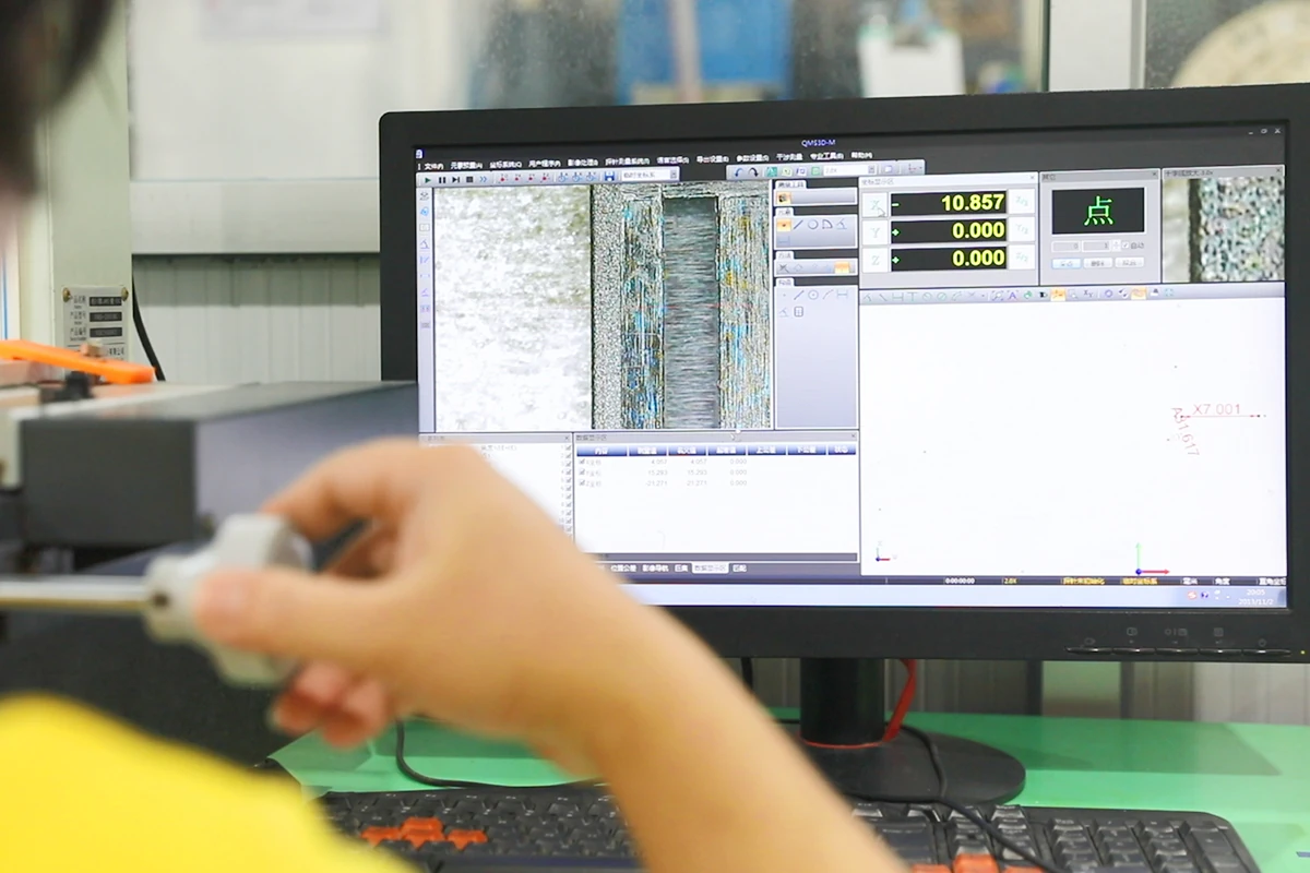
For relevant projects, FPIC can verify cable length, branch position, connector orientation, terminal position, labeling, wiring sequence, and other defined characteristics. Documented equipment includes dimensional measurement systems, cable harness testers, contact-impedance instruments, withstand-voltage and insulation testers, and a servo tensile tester. The required inspection and test scope is established according to the product structure, customer drawing, application, and agreed standards rather than applying every available test to every assembly.
FPIC also uses PLM, ERP, MES, and WMS to support engineering data, production, materials, and records. These systems help keep the approved drawing and BOM aligned with the work order, instructions, inspection status, and batch history.
Customers developing a new assembly can use FPIC’s OEM/ODM wire harness services to coordinate manufacturability review, prototyping, inspection planning, and production transfer. The manufacturing capability and testing resources can then be matched to the actual project requirements.
What OEM Buyers Should Define Before Production Approval
An effective FAI begins with clear requirements. Before placing a production order, engineering and procurement teams should provide or agree on:
- Released 2D drawings, wiring diagrams, pin maps, and BOM revisions
- Approved manufacturer part numbers and any permitted alternatives
- Dimensional datums, tolerances, and measurement conditions
- Workmanship standard and product class where applicable
- Crimp, pull-force, cross-section, or retention requirements where applicable
- Electrical test scope, limits, and test-program approval method
- Required material, inspection, and traceability records
- Packaging, labeling, and serialization requirements
- Customer approval authority and rules for deviations
- Events requiring partial or full reapproval
Procurement should also ask whether the quoted price and lead time include destructive test specimens, special fixtures, customer-specific reports, third-party tests, or formal submission packages. Clarifying these items during quotation is more efficient than adding them after the production plan has been established.
Conclusion
First article inspection is valuable because it turns a released design into objective production evidence. It verifies that documents agree, specified materials are present, dimensions and workmanship meet requirements, terminations have been validated, the electrical test program is correct, and the resulting records can support repeatable manufacturing.
The strongest FAI is neither a quick visual check nor an oversized paperwork exercise. It is a risk-based, characteristic-level approval using the methods appropriate to the assembly. When a relevant engineering or process change occurs, the affected evidence must be reviewed again before the previous baseline is assumed to remain valid.
If you are preparing a custom cable assembly for prototype, pilot, or volume production, send FPIC your project requirements. Include the drawing, BOM, pin definition, cable specifications, required quantity, application conditions, inspection criteria, and documentation needs. FPIC can review the manufacturability and production-approval scope for your project.
Email: info@sz-fpi.com
Frequently Asked Questions
What is first article inspection for a wire harness?
It is a documented comparison of representative initial production output against the released drawing, BOM, workmanship criteria, and agreed test requirements. The scope should cover every applicable characteristic using suitable visual, dimensional, mechanical, electrical, and document-review methods.
Is a prototype the same as an approved first article?
Not necessarily. A prototype may evaluate design fit or function using temporary materials, tooling, or manual processes. An approved first article should represent the configuration and production process intended for the order unless the customer has formally accepted defined differences.
Does every wire harness require an AS9102 report?
No. AS9102C is an aerospace first-article standard and applies when required by the customer, contract, or relevant quality system. Other harness projects may use a customer form or a controlled supplier checklist based on the drawing and agreed quality plan.
Should crimp pull testing be performed on the delivered first article?
Normally, destructive pull testing is performed on dedicated specimens rather than the saleable assembly. The specimen configuration, method, frequency, and acceptance value must follow the applicable terminal specification, customer requirement, standard, or validated control plan.
Can a previously approved harness require another FAI?
Yes. A drawing or BOM revision, material substitution, tooling repair, process transfer, test-program change, extended production interruption, or corrective action may require full or partial reapproval. The decision should reflect the characteristics affected by the change.
What should a customer submit for FAI planning?
Provide the released drawing, BOM, wiring diagram or pin map, approved component information, dimensional tolerances, workmanship criteria, test requirements, documentation format, application conditions, and approval authority. Identifying change-control expectations early also prevents later disputes.
Resources
- IPC – IPC/WHMA-A-620F Standard
IPC identifies IPC/WHMA-A-620F as its current cable and wire harness assembly standard covering materials, methods, tests, and acceptance criteria. - SAE International – AS9102C First Article Inspection Requirements
The official SAE page identifies AS9102C as the standard establishing requirements for performing and documenting aerospace first article inspection. - IEC – IEC 60352-2:2024 Solderless Crimped Connections
The IEC publication provides general requirements, test methods, and practical guidance for solderless crimped connections within its defined conductor and product scope. - TE Connectivity – Application Tooling Literature
TE’s official tooling resource identifies crimp height, pull-test values, throughput, and crimp symmetry as measurements used to monitor termination processes. - Komax – Crimp Height Measuring
Komax describes crimp-height measurement as a precise, repeatable method for detecting deviations and supporting consistent crimp quality.