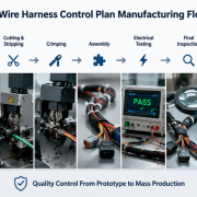
Wire Harness Process Control Plan: From Incoming Material to Final Inspection
A reliable wire harness does not become high quality through final inspection alone. Its performance depends on a series of controlled manufacturing operations, from verifying incoming materials to cutting, stripping, crimping, connector assembly, protective covering, electrical testing, and final inspection.
If a wire is cut to the wrong length, a terminal is incorrectly crimped, or a connector cavity is populated incorrectly, the resulting defect may pass through several production stages before it is detected. This can increase rework costs, disrupt delivery schedules, and create risks for the finished assembly.
A wire harness process control plan helps prevent these problems by defining what must be controlled at each production stage, how conformity is verified, who is responsible, and what actions are required when a result falls outside the approved criteria.
This article explains how to build a practical control plan for wire harness manufacturing, including an example process-control matrix that can be adapted to different products and production environments.
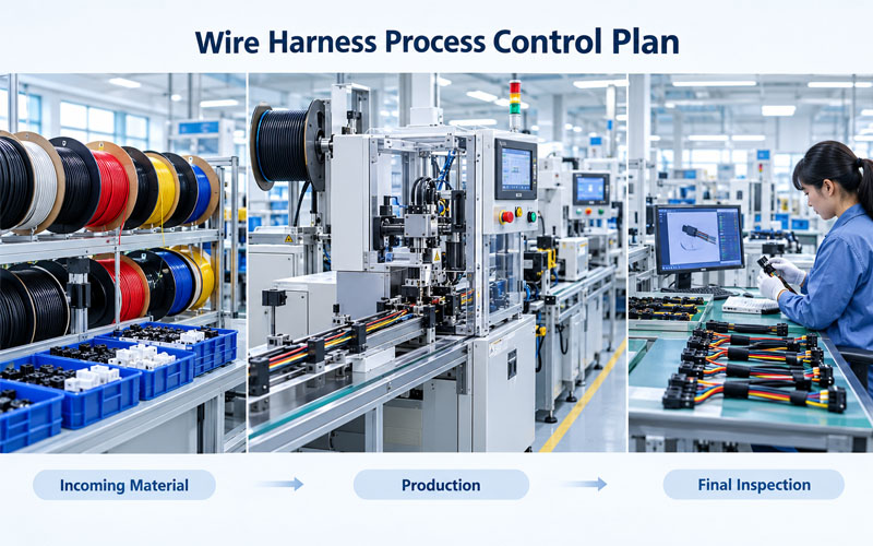
1.What Is a Wire Harness Process Control Plan?
A process control plan is a structured manufacturing document that connects product requirements with production controls and inspection activities.
For a wire harness manufacturer, it should identify the critical characteristics of each process, the applicable specifications, the inspection or monitoring method, the required records, and the response to nonconforming results.
A practical control plan normally includes:
- Manufacturing process step and sequence.
- Product or process characteristics requiring control.
- Applicable drawings, specifications, and acceptance criteria.
- Inspection or monitoring method.
- Control frequency or sampling plan.
- Responsible personnel or function.
- Required records and traceability information.
- Reaction plan for deviations and nonconforming products.
The exact content depends on the product, customer requirements, manufacturing process, and risk level.
For example, a simple two-wire cable assembly may need a relatively straightforward set of controls. A complex industrial harness containing multiple connectors, shielded cables, branch points, and high-current conductors may require additional checks for routing, terminal compatibility, shielding termination, and electrical performance.
Process control plan vs. inspection checklist vs. PFMEA
These documents support one another but serve different purposes.
| Document | Primary purpose | Typical question answered |
|---|---|---|
| PFMEA | Identify and evaluate potential process failures | What could go wrong, and what are the risks? |
| Process control plan | Define how important characteristics are controlled | What must be controlled, how, and when? |
| Inspection checklist | Record specific inspection results | Did this item or operation pass the required check? |
| Work instruction | Standardize how an operation is performed | How should the operator perform the task? |
The PFMEA should inform the control plan, particularly when identifying critical process characteristics and appropriate controls. Inspection checklists and work instructions then help personnel execute those controls consistently.
A control plan should not simply list every manufacturing step. It should emphasize the characteristics and failure risks that require defined controls.
2.Define the Control Plan Before Production Starts
Before assigning inspection methods or sampling frequencies, establish the technical basis for the plan.
2.1 Review the product requirements
Start with the latest approved product drawing, bill of materials, wiring diagram, customer specifications, and applicable workmanship or testing requirements.
Identify requirements such as:
- Wire type, cross-section, color, and specified length.
- Terminal and connector part numbers.
- Pin assignments and circuit mapping.
- Crimp specifications and approved tooling.
- Stripping dimensions and conductor preparation.
- Branch locations and wire routing.
- Shielding, sleeving, sealing, and strain relief.
- Labels, markings, and identification requirements.
- Electrical test limits and final acceptance criteria.
Requirements should be measurable wherever possible. Terms such as “proper crimp” or “correct assembly” are not sufficient unless they refer to a defined acceptance standard or documented work instruction.
2.2 Identify critical characteristics
Not every characteristic needs the same inspection method or frequency.
A useful approach is to classify requirements according to their impact on product function, safety, reliability, and customer acceptance.
For example:
- Incorrect wire length may prevent proper installation.
- Incorrect pin assignment may cause circuit malfunction.
- Poor crimp quality may increase resistance or reduce mechanical retention.
- Inadequate insulation or shielding preparation may compromise electrical performance.
- Incorrect labels may create installation, maintenance, or traceability problems.
The control plan should prioritize these risks and define suitable preventive and detection controls.
2.3 Establish measurable acceptance criteria
Acceptance criteria should come from approved drawings, engineering specifications, customer requirements, applicable standards, and validated process documentation.
Do not invent universal limits for wire length, crimp height, pull force, insulation resistance, or other characteristics. These values depend on the actual product and test requirements.
Where a requirement is not yet defined, resolve it through engineering review before production release.
3.Incoming Material Inspection: Control Quality Before Processing
Incoming inspection is the first opportunity to prevent unsuitable materials from entering production.
However, inspection should not rely only on a supplier label or purchase order description. The receiving process needs a defined method for confirming material identity, condition, and applicable documentation.
3.1 Verify material identity and revision
Check incoming materials against the approved bill of materials and purchasing requirements.
Depending on the material, verification may include:
- Wire and cable part number, cross-section, color, and specification.
- Terminal and connector part number and revision.
- Seal, grommet, sleeve, tape, conduit, and protective covering specifications.
- Approved supplier status and material lot identification.
- Required certificates, test reports, or compliance documentation.
For terminals and connectors, confirm that the supplied components match the approved design and are suitable for the intended conductor and application.
3.2 Inspect physical condition
Check for visible damage, deformation, contamination, corrosion, damaged packaging, or other conditions that could affect assembly quality.
For wire and cable, inspect the insulation for cuts, crushing, or other damage when required by the incoming inspection procedure. For terminals, check for bent contacts, damaged plating, or deformation that could interfere with termination or mating.
Visual checks alone cannot establish every material property. Additional verification should be applied where required by the specification or supplier-control plan.
3.3 Maintain material status and traceability
Materials that have not been accepted should remain clearly identified and controlled to prevent unintended use.
A practical receiving process records the material identification, supplier or lot information, inspection status, and disposition of nonconforming items.
Key control principle: Materials should not be released to production until the required verification and acceptance steps have been completed.
4.Cutting and Stripping: Control Wire Dimensions and Preparation
Cutting and stripping determine the initial dimensions and condition of each wire. Errors at this stage can affect later crimping, routing, assembly, and installation.
4.1 Wire cutting control
Important characteristics include:
- Correct wire specification and color.
- Cut length within the approved tolerance.
- Correct quantity for the production order.
- Clean cut ends without unacceptable conductor damage.
- Correct identification of wires used in multi-circuit assemblies.
Use suitable measuring equipment or calibrated processing systems according to the control requirements. Where automated cutting equipment is used, setup verification and periodic checks help confirm that programmed values match the approved job.
4.2 Stripping control
Stripping should expose the specified conductor length while preserving the conductor strands and insulation.
Inspection should address:
- Strip length.
- Insulation damage or excessive deformation.
- Cut, nicked, or missing conductor strands.
- Residual insulation or other contamination.
- Compatibility between the stripping tool and wire construction.
For fine-stranded or specialized cables, stripping parameters may need to be validated for the specific conductor and insulation construction.
A correct strip length does not automatically mean the wire is ready for termination. Strand condition and cleanliness may also require verification.
4.3 Control changes between jobs
When changing wire type, cross-section, color, or processing settings, verify that the equipment configuration and work instructions correspond to the new production order.
A first-piece check can help identify incorrect programs, tooling, or material selection before the issue affects a larger batch.
5.Crimping: Control the Most Critical Connection Process
Crimping is a key control point because it directly affects the mechanical retention and electrical connection between the conductor and terminal.
A defect may be difficult to identify through appearance alone, so crimp control should combine approved tooling, process settings, dimensional checks, and appropriate verification testing.
5.1 Verify terminal and tooling compatibility
Before crimping, confirm the conductor, terminal, applicator or die, and machine setup against the approved process documentation.
Check that the tooling is suitable for the terminal design and conductor construction. Similar nominal wire sizes do not necessarily mean that different terminal systems can use the same crimp tooling or settings.
5.2 Control crimp dimensions and appearance
Depending on the terminal design, relevant checks may include:
- Crimp height or other specified crimp dimensions.
- Conductor insertion and position.
- Terminal deformation and alignment.
- Insulation support, where applicable.
- Visible strand damage or unacceptable conductor exposure.
- Tooling condition and process setup.
Use the specified measurement method and acceptance criteria. Crimp height should not be treated as a universal indicator that every aspect of the connection is acceptable.
5.3 Apply mechanical and electrical verification
Pull force testing can help evaluate mechanical retention, while cross-section analysis can reveal internal crimp geometry when required.
Electrical resistance or other application-specific tests may also be needed to verify performance. The selected methods should reflect the terminal design, risk assessment, and customer requirements.
The control plan should specify when these checks are required, how results are recorded, and what happens after a failure.
5.4 Define the reaction plan
If a crimp measurement or test falls outside its approved limits, production personnel should follow a documented response.
This may include stopping the affected operation, identifying potentially affected parts, containing the relevant batch, investigating the tooling and material condition, and verifying the corrective action before restarting.
Adjusting a machine until a sample passes is not sufficient without determining whether the underlying cause has been addressed.
6.Connector Assembly and Circuit Verification
Connector assembly introduces additional risks, including incorrect cavity assignments, terminal insertion problems, damaged seals, and incomplete secondary locking.
6.1 Control connector and terminal selection
Confirm the connector housing, terminal, seal, cavity plug, and other components against the approved bill of materials.
Where a connector family has multiple variants, visual similarity should not be used as the only identification method. Part-number verification and controlled material presentation reduce the risk of mixing incompatible components.
6.2 Verify terminal insertion and retention
Check terminal position, orientation, and seating according to the applicable assembly requirements.
Depending on the connector design, controls may include:
- Correct cavity assignment.
- Complete terminal insertion.
- Primary locking engagement.
- Secondary lock installation and position.
- Seal placement and condition.
- Absence of bent or damaged contacts.
Where applicable, use a specified retention test or approved verification method rather than relying solely on an informal pull by hand.
6.3 Verify circuit mapping
For multi-circuit assemblies, the correct wire must connect to the intended terminal cavities at both ends.
Circuit mapping should be verified against the approved wiring diagram or test program. Automated electrical testing can help detect open circuits, short circuits, and miswiring that may not be apparent from a visual inspection.
This control is particularly important for assemblies with similar connector housings, multiple branches, or complex pin assignments.
7.Harness Assembly, Routing, and Protective Coverings
After individual wires and connectors are prepared, the assembly process must preserve the intended physical layout and protection.
7.1 Control wire routing and branch dimensions
Use the approved assembly drawing, fixture, or board layout to verify wire paths, branch points, and relevant dimensions.
Inspect for incorrect routing, crossed wires, excessive tension, and unintended interference between components.
For assemblies with defined bend-radius requirements, verify that the routing does not force the cable beyond the applicable limits.
7.2 Verify securing and protective components
Cable ties, clips, sleeves, conduits, heat-shrink tubing, and other protective components should match the specified type, position, and installation requirements.
Check that securing methods do not damage insulation or apply excessive pressure to sensitive wires.
For shielded assemblies, verify the specified shielding preparation and termination method. For sealed products, inspect the relevant sealing components and assembly conditions according to the design requirements.
7.3 Check labels and markings
Verify that labels, wire identification, and connector markings are correct, readable, and positioned as specified.
Where barcode or QR-code identification is used, confirm that the identifier matches the correct part or production record.
These checks support installation accuracy and product traceability, but they should not replace electrical or mechanical verification.
8.Electrical Testing and Final Inspection
Final inspection should confirm that the completed harness meets its defined acceptance requirements. It should also verify that the required process checks and test records have been completed.
8.1 Electrical testing
The required electrical test plan depends on the product design and application. It may include:
- Continuity testing.
- Open-circuit and short-circuit detection.
- Pin-to-pin mapping verification.
- Insulation resistance testing.
- Dielectric withstand testing, where specified.
- Additional functional or performance tests.
These tests are not interchangeable. For example, continuity confirms an electrical path but does not, by itself, demonstrate adequate insulation resistance or acceptable high-current connection performance.
Test voltage, limits, sequence, and acceptance criteria must follow the applicable product requirements and approved test procedure.
8.2 Visual and dimensional final inspection
Final inspection may verify:
- Correct connectors and accessories.
- Complete assembly and correct branch layout.
- Terminal and secondary-lock positions, where applicable.
- Protective coverings and securing components.
- Labels and identification.
- Overall dimensions and specified interfaces.
- Visible damage, contamination, or workmanship defects.
Final inspection should use clear acceptance criteria and the approved inspection method.
8.3 Review records before release
The final release process should confirm that the required inspections and tests have been completed and that any nonconformities have been properly resolved.
Where traceability is required, connect the finished assembly or batch to the relevant material lots, production records, test results, and disposition history.
A product should not be released merely because it looks acceptable if required tests or documentation remain incomplete.
9.Example Wire Harness Process Control Plan
The following table is a practical starting point for developing a product-specific plan. It is not a universal inspection specification; the actual control methods, frequencies, and acceptance criteria should be established from the product requirements, process risk, and customer agreement.
| Process stage | Key characteristics to control | Typical control method | Reaction to nonconformity |
|---|---|---|---|
| Incoming materials | Part number, specification, condition, lot identification | Document review, identification check, visual inspection, specified incoming tests | Hold material, identify the affected lot, and obtain disposition |
| Wire cutting | Wire type, color, cut length, quantity | Setup verification, dimensional measurement, program check | Stop or correct setup; assess wires produced since the last acceptable check |
| Wire stripping | Strip length, insulation condition, conductor strand condition | Visual inspection and dimensional measurement | Segregate affected wires and correct tooling or settings |
| Crimping | Terminal compatibility, crimp dimensions, conductor position, workmanship | Setup verification, crimp measurement, visual inspection, specified mechanical tests | Contain affected parts, investigate cause, and revalidate the process |
| Connector assembly | Cavity assignment, terminal seating, locks, seals | Drawing comparison, visual inspection, approved retention checks | Correct or replace affected components and recheck the assembly |
| Harness assembly | Routing, branch dimensions, securing, protective coverings | Assembly fixture or board comparison, dimensional and visual checks | Rework according to approved instructions and reinspect |
| Marking and labeling | Identification accuracy, readability, location | Visual verification and barcode or QR-code check where applicable | Correct identification and verify against the production record |
| Electrical testing | Continuity, circuit mapping, shorts, insulation or other specified parameters | Approved electrical test equipment and test program | Fail and contain the unit; diagnose the cause and retest after authorized correction |
| Final inspection | Completeness, dimensions, workmanship, accessories, records | Final inspection checklist and document review | Prevent release until the issue is resolved and acceptance is documented |
How to set inspection frequency
Inspection frequency should be defined for each control rather than copied from a generic template.
Possible approaches include:
- Setup verification: Check the first piece or initial samples after a job change, tooling change, or equipment setup.
- Periodic inspection: Perform dimensional or visual checks at defined intervals based on process risk and stability.
- Continuous or automated monitoring: Use equipment-based monitoring where the method is validated and the limits are documented.
- Lot-based or sample testing: Apply an approved sampling plan for tests that are destructive, time-consuming, or otherwise unsuitable for every unit.
- 100% inspection or testing: Use when required by the product specification, customer requirements, risk assessment, or validated control strategy.
A 100% test does not eliminate every risk. Test coverage, fixture condition, program validation, measurement capability, and the types of defects detectable by the method must also be considered.
10.Manage Nonconforming Products and Process Changes
A process control plan is effective only when it defines what happens when a control fails.
10.1 Establish a clear nonconformance workflow
A practical workflow should cover:
- Detection: Identify the failed measurement, inspection, or test.
- Containment: Prevent potentially affected products from moving forward or being shipped.
- Scope assessment: Determine the affected time period, batch, materials, tooling, and production orders.
- Root-cause analysis: Investigate why the failure occurred rather than correcting only the visible symptom.
- Corrective action: Implement and verify an appropriate process or material correction.
- Release authorization: Resume production or release affected products only after the defined requirements are satisfied.
- Documentation: Record the issue, disposition, and verification results.
Rework should follow approved instructions, especially when it could affect terminal retention, insulation integrity, sealing, or electrical performance.
10.2 Review changes that can affect quality
The control plan should be reviewed when relevant changes occur, including:
- New wire, terminal, connector, or protective material.
- Revised product drawings or wiring diagrams.
- New or modified tooling and equipment.
- Changes to crimp settings or test programs.
- Supplier changes or recurring material defects.
- Repeated inspection failures or customer complaints.
A change does not always require repeating every validation activity. Engineering and quality personnel should determine the appropriate scope based on the potential impact and applicable requirements.
11.Keep the Control Plan Practical and Up to Date
A control plan should be usable on the production floor, not simply stored as a document for audits.
To make it effective:
- Assign clear responsibility for each control.
- Link inspection criteria to current drawings and work instructions.
- Use consistent terminology across engineering, production, and quality records.
- Make sampling frequency and reaction instructions unambiguous.
- Train operators and inspectors on the relevant acceptance criteria.
- Review recurring defects and process trends.
- Update the plan after approved engineering or process changes.
For manufacturers using digital production systems, inspection results can be linked to work orders, material batches, equipment, and finished-product identifiers. Barcode or QR-code scanning can help improve record accuracy and make investigations more efficient.
However, digital records do not replace sound process design. The underlying inspection methods, acceptance criteria, and reaction plans must still be technically appropriate.
12.Standards and Customer-Specific Requirements
IPC/WHMA-A-620 is an important industry reference for cable and wire harness assembly workmanship. IPC describes it as covering materials, methods, tests, and acceptability criteria for cable and harness assemblies. It also notes that the standard does not prescribe inspection frequency for every process or product. IPC standards overview
This distinction matters when developing a control plan: an applicable workmanship standard may define acceptance requirements, while the manufacturer and customer still need to establish suitable process controls, sampling frequencies, and records for the particular product.
Where relevant, use the applicable revision of IPC/WHMA-A-620 alongside approved drawings, customer specifications, and other product-specific requirements. Do not assume that one standard covers every electrical, environmental, mechanical, or application-specific validation need.
How FPIC Approaches Wire Harness Quality Control
For customized wire harnesses, quality control begins with clear product requirements and continues through controlled manufacturing and verification.
FPIC supports customized wire harness and cable assembly projects for industrial, medical, automotive, and energy-related applications. Defining the intended application, cable and terminal specifications, assembly requirements, and testing expectations early helps align manufacturing controls with the needs of the finished product.
For complex or high-reliability assemblies, customers and manufacturers should agree on critical characteristics, acceptance criteria, test coverage, traceability requirements, and change-control responsibilities before production release.
Conclusion
A wire harness process control plan provides a structured way to manage manufacturing quality from incoming materials to final inspection.
The most effective plans identify critical characteristics at each stage, define measurable acceptance criteria, select suitable inspection and testing methods, and establish clear reactions to nonconformities. They also connect process controls with engineering specifications, work instructions, and traceability records.
Rather than relying on final inspection to catch every defect, manufacturers should build quality into each operation and verify that the controls remain effective throughout production.
A well-maintained control plan helps reduce avoidable rework, improve manufacturing consistency, and provide stronger evidence that finished wire harnesses meet their defined requirements.
FAQ
What should a wire harness process control plan include?
It should identify manufacturing stages, critical product and process characteristics, applicable specifications, inspection or monitoring methods, control frequencies, responsible personnel, required records, and reaction plans for nonconformities.
What is the difference between a control plan and a PFMEA?
A PFMEA identifies potential process failures and evaluates their risks. A control plan defines the controls used to prevent or detect those failures and how the results are managed during production.
Should every wire harness process have 100% inspection?
No. Inspection coverage should be determined by product requirements, process risk, customer expectations, and the capability of the inspection method. Some characteristics require 100% verification, while others may be controlled through validated sampling or process monitoring.
Which standard is commonly used for wire harness workmanship?
IPC/WHMA-A-620 is a widely used industry standard for cable and wire harness assembly workmanship and acceptance. The applicable revision and any additional customer-specific requirements should be confirmed for each project.
How should a manufacturer respond when a wire harness fails electrical testing?
The affected assembly should be identified and contained according to the control plan. The manufacturer should investigate the failure, assess whether other units may be affected, perform authorized correction or rework, and verify compliance before release. Required actions and results should be documented.
How often should a wire harness control plan be updated?
Review it whenever product specifications, materials, tooling, equipment, test programs, or manufacturing methods change in ways that could affect quality. Recurring defects, customer feedback, and process-performance data should also trigger a review when they indicate that existing controls may be inadequate.
Need a wire harness manufacturing partner for your next project?
Share your drawings, wiring diagrams, application requirements, and inspection expectations with FPIC. Early alignment on critical characteristics, process controls, and final testing helps establish a clear path from prototype development to consistent production.
Contact FPIC to discuss your customized wire harness requirements.
Resources
- IPC – Meet Your Standards
Official overview of IPC industry standards, including IPC/WHMA-A-620 and its role in cable and wire harness assembly workmanship and acceptance. - IPC – IPC/WHMA-A-620E: Requirements and Acceptance for Cable and Wire Harness Assemblies
Explains the scope of Revision E and the workmanship requirements covered for cable and wire harness manufacturing. - IPC – IPC/WHMA-A-620 Endorsement Program
Provides an overview of the standard’s training topics, including crimp terminations, testing, marking, labeling, shielding, and protective coverings. - IPC – IPC Document Revision Table
Useful for checking published revisions of relevant IPC standards and confirming the document version applicable to a project.