How EMI Shielding Improves Industrial Wire Harness Reliability
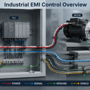
Industrial equipment increasingly combines motors, drives, sensors, controllers, communication networks, power electronics, and high-speed data interfaces within the same machine.
As electrical systems become more compact and interconnected, electromagnetic interference (EMI) becomes a significant wire harness design consideration.
A wire harness does not simply transmit power or signals. It can also become a path through which electromagnetic noise is coupled into sensitive circuits or radiated into the surrounding environment.
Proper EMI shielding can help reduce unwanted interference, protect signal integrity, and improve the reliability of industrial equipment.
Why EMI Matters in Industrial Wire Harnesses
Industrial equipment often contains multiple potential sources of electromagnetic noise, including:
- Servo motors
- Variable frequency drives
- Switching power supplies
- Inverters
- Relays and contactors
- High-current power cables
- Industrial Ethernet systems
- High-speed communication interfaces
At the same time, sensitive circuits such as sensors, encoders, PLC inputs, cameras, and communication lines can be affected by unwanted electromagnetic energy.
EMI can result in:
- Signal distortion
- Communication errors
- Sensor instability
- Encoder errors
- Unexpected controller behavior
- Data transmission interruptions
- Intermittent system faults
EMC is ultimately a system-level consideration: equipment must operate properly in its electromagnetic environment without creating unacceptable interference for other equipment.
For this reason, EMI control should be considered during wire harness design rather than treated as a corrective measure after system testing.
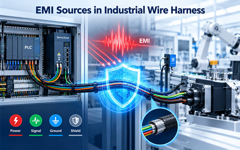
1.How EMI Enters a Wire Harness
EMI can be coupled into a harness through several mechanisms.
Conducted Interference
Electrical noise can travel directly through power or signal conductors.
For example, switching devices and motor drives can generate high-frequency disturbances that propagate through connected wiring.
Capacitive Coupling
A changing voltage on one conductor can couple energy into a nearby conductor, particularly when the wires run parallel over a long distance.
Inductive Coupling
Changing current can generate a magnetic field that induces unwanted voltage in nearby conductors.
This is particularly important when sensitive signal wiring is routed close to high-current or motor wiring.
Radiated Interference
Electromagnetic energy can also propagate through the surrounding environment and couple into exposed wiring.
This becomes increasingly important as equipment contains higher-frequency switching and communication systems.
2.What EMI Shielding Does
An effective cable shield creates a conductive barrier around sensitive conductors.
Depending on the cable construction and application, shielding may use:
- Braided copper
- Foil shielding
- Spiral shielding
- Combination foil and braid
- Shielded twisted pairs
- Multi-layer shielding structures
The purpose is not simply to “add metal” around the wires.
The shielding system must be designed as a complete structure involving:
Shield material + coverage + termination + grounding + routing + mechanical protection
A weakness in any of these areas can reduce overall performance.
TE Connectivity notes that shielding performance depends on factors such as material, installation, grounding, frequency, and test method.
3.Shield Coverage and Cable Construction
Shield coverage is an important consideration when selecting a cable for industrial applications.
A higher coverage structure can provide better protection against electromagnetic coupling, but cable flexibility, diameter, weight, cost, and manufacturing requirements must also be considered.
For dynamic applications, the shield must additionally withstand:
- Repeated bending
- Torsion
- Vibration
- Temperature changes
- Mechanical movement
A cable that provides good EMI performance in a laboratory but loses shield continuity during repeated motion may not provide reliable protection in the actual machine.
Therefore, electrical shielding performance and mechanical durability should be evaluated together.
4.Shield Termination Is Often the Critical Point
One of the most overlooked aspects of EMI protection is shield termination.
A cable may have excellent shielding along its length, but poor termination can create a weak point at the connector or equipment interface.
Typical termination methods include:
- 360° shield termination
- Shield clamps
- Conductive backshells
- Shield crimp rings
- Drain wire connections
- Conductive connector interfaces
The appropriate method depends on cable construction, frequency range, mechanical requirements, and equipment architecture.
For example, industrial communication cable assemblies may use 360° shielding to improve EMI performance and maintain signal integrity.
Why 360° Termination Matters
A short pigtail connection may introduce additional inductance at higher frequencies.
A properly designed circumferential termination can provide a more continuous shielding path between the cable and the equipment interface.
This is particularly important for high-speed industrial communication systems and other noise-sensitive applications.
5.Grounding and Shielding Must Be Considered Together
Shielding cannot be evaluated independently from grounding.
The shield needs an appropriate electrical reference and termination strategy based on the system architecture and frequency range.
Poor grounding or an unintended current path can reduce shielding effectiveness or introduce additional noise.
Important design questions include:
- Where should the shield terminate?
- Should the shield be connected at one or both ends?
- What grounding architecture does the equipment use?
- Is a chassis connection available?
- What frequency range is involved?
- Are there potential ground-loop concerns?
- How will the shield connection behave during vibration and environmental exposure?
There is no universal grounding rule that applies to every industrial harness.
The correct approach depends on the complete electrical system.
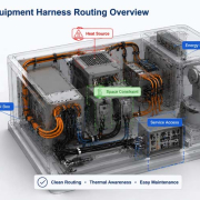
6.Harness Routing Can Make or Break EMI Performance
Even a well-shielded cable can experience EMI problems if routing is poorly designed.
Sensitive signal and communication cables should generally be routed with appropriate separation from strong noise sources such as:
- Servo motor cables
- VFD output cables
- High-current conductors
- Switching power circuits
- Contactors and relays
Where separation cannot be maintained, the harness architecture should consider shielding, orientation, crossing strategy, and other EMC control methods.
Parallel Routing
Long parallel runs between noisy power cables and sensitive signal cables can increase unwanted coupling.
Where practical, reduce the length of parallel exposure or introduce appropriate physical separation.
Crossing Conductors
Where power and signal cables must cross, the routing strategy should minimize unwanted coupling while maintaining mechanical and installation requirements.
The goal is not simply to create a visually organized harness.
The goal is to control the electromagnetic environment around the harness.
7.Shielding for Industrial Communication Cables
High-speed communication systems can be particularly sensitive to EMI.
Industrial Ethernet, encoder signals, machine vision interfaces, and other high-speed communication systems require stable signal transmission.
For example, industrial machine vision applications may require full-length cable shielding to support signal performance and EMI reduction.
Potential symptoms of poor EMI control include:
- Intermittent communication loss
- Packet errors
- Image instability
- Encoder signal errors
- Increased retransmissions
- Unexpected equipment stops
These failures can be difficult to diagnose because the harness may pass a basic continuity test even when its EMC performance is inadequate.
8.Mechanical Reliability of the Shield
EMI performance is not purely an electrical issue.
The shielding structure must also survive the mechanical environment.
Industrial harnesses may experience:
- Continuous vibration
- Repeated bending
- Torsion
- Abrasion
- Temperature cycling
- Oil or chemical exposure
- Installation stress
Mechanical damage to the braid or foil can change shielding continuity.
For moving applications, shield construction should therefore be selected together with the required flex life and bend performance.
This is especially important for robotics, servo systems, automated machinery, and drag-chain applications.
9.Shielding and Strain Relief Should Work Together
The cable shield should not carry mechanical loads that are better handled by the harness structure.
A properly designed assembly should provide suitable:
- Strain relief
- Cable support
- Backshell protection
- Bend control
- Clamp positioning
- Connector retention
This prevents repeated mechanical forces from being transferred directly into the shield termination.
A strong shield termination that is mechanically unsupported can still become unreliable after repeated movement.
10.EMI Shielding Must Be Validated at System Level
A shielding design should not be considered successful simply because a shielded cable was selected.
Validation should consider the complete assembly.
Important factors include:
Electrical Tests
- Shield continuity
- Insulation resistance
- HiPot where applicable
- Signal integrity
- Communication performance
EMC-Related Evaluation
Depending on the application:
- Radiated emissions
- Conducted emissions
- Radiated immunity
- Conducted immunity
- System-level EMC testing
Mechanical Testing
- Vibration
- Flexing
- Torsion
- Bend cycling
- Connector retention
- Shield termination durability
IPC/WHMA-A-620 includes requirements related to electrical shielding, braided shielding, shield termination, protective coverings, and finished cable assembly installation.
The important principle is to validate the finished harness, not only individual components.
11.Common EMI Shielding Mistakes
Several design mistakes appear repeatedly in industrial harness applications.
Mistake 1: Shielding Only the Cable
Adding a shielded cable without reviewing routing and termination may not solve the actual EMI problem.
Mistake 2: Poor Shield Termination
A weak termination can create an electromagnetic discontinuity at the connector interface.
Mistake 3: Long Unshielded Sections
Even a shielded harness can lose effectiveness if significant portions of the signal path are left exposed.
Mistake 4: Ignoring Mechanical Stress
Repeated bending or vibration can damage shielding and termination structures.
Mistake 5: Testing Only Continuity
Continuity confirms electrical connection, but it does not automatically confirm EMC performance.
Mistake 6: Adding Shielding Too Late
EMC problems discovered during final system testing can require expensive harness and equipment redesign.
TE Connectivity similarly recommends considering EMC early in the design process because late-stage modifications can be costly.
12.A Practical EMI Shielding Design Workflow
A practical industrial wire harness workflow can include the following steps:
Step 1 — Identify Noise Sources
Map motors, drives, switching circuits, and other potential EMI sources.
Step 2 — Identify Sensitive Circuits
Define sensors, communication interfaces, encoders, cameras, and other noise-sensitive circuits.
Step 3 — Define Routing Zones
Separate high-noise and low-noise wiring wherever practical.
Step 4 — Select Shielding Construction
Consider braid, foil, combination shielding, cable flexibility, and environmental requirements.
Step 5 — Design Shield Termination
Select an appropriate termination method for the cable and connector system.
Step 6 — Integrate Strain Relief
Prevent mechanical loads from damaging shield termination points.
Step 7 — Validate the Finished Assembly
Evaluate electrical, mechanical, signal integrity, and EMC performance under realistic conditions.
This approach treats EMI shielding as part of the overall harness architecture, rather than as an isolated cable feature.
How FPIC Approaches EMI-Controlled Wire Harnesses
For industrial wire harness applications, EMI control needs to be balanced with routing space, mechanical durability, assembly requirements, and serviceability.
FPIC can support customized cable and wire harness assemblies for industrial automation and other demanding applications, with design considerations covering cable construction, shielding, termination, routing, and assembly requirements.
The objective is not simply to make a harness that works electrically.
It is to develop a harness that maintains signal integrity and mechanical reliability throughout the expected operating environment.
Final Thoughts
EMI shielding is an important part of reliable industrial wire harness design.
However, shielding performance depends on more than the cable itself.
Shield construction, termination, grounding, routing, mechanical protection, and system-level validation must work together.
For industrial automation, communication, robotics, machine vision, and other electrically complex systems, a well-designed EMI strategy can reduce interference-related failures and improve long-term equipment reliability.
The most effective approach is to consider EMI during the early harness design stage—before routing, termination, and equipment architecture become difficult to change.
FAQ
What is EMI shielding in a wire harness?
EMI shielding uses conductive materials around cables or conductors to reduce unwanted electromagnetic coupling and protect sensitive signals from interference.
Does every industrial wire harness need EMI shielding?
No. The requirement depends on the electrical environment, signal sensitivity, noise sources, cable length, operating frequency, and EMC requirements of the equipment.
Is braided shielding better than foil shielding?
Neither is universally better. Braid, foil, or combination shielding should be selected according to frequency range, flexibility, coverage, mechanical requirements, and application conditions.
Why is shield termination important?
The termination connects the cable shield to the equipment or connector interface. Poor termination can create a weak point that reduces overall shielding performance.
Can EMI shielding prevent all interference?
No. Shielding is one part of an EMC strategy. Routing, grounding, filtering, circuit design, enclosure design, and system-level validation may also be required.
How should EMI shielding be tested?
Testing should be application-specific and may include shield continuity, signal integrity, mechanical durability, emissions, immunity, and other EMC evaluations.
Need a Reliable Industrial Wire Harness with EMI Shielding?
FPIC provides customized wire harness and cable assembly solutions for industrial automation, communication, robotics, machine vision, and other demanding applications.
Contact FPIC to discuss your cable construction, shielding, routing, termination, and application requirements.
Resources
- TE Connectivity – Electromagnetic Compatibility: Overview of EMC principles, EMI control methods, shielding, and the importance of considering EMC during early design.
- TE Connectivity – EMI Shielding FAQs: Covers shielding effectiveness, grounding, material selection, environmental factors, and common EMI considerations.
- IPC/WHMA-A-620 – Requirements and Acceptance for Cable and Wire Harness Assemblies: Industry reference covering cable and wire harness assembly practices, materials, methods, testing, and acceptance criteria.
- IPC/WHMA-A-620 Operator Training – Electrical Shielding and Protective Coverings: Includes training content related to braided shielding, shield termination, protective coverings, and cable assembly installation.
- Molex – Machine Vision System Design: Industrial machine vision reference highlighting signal integrity, cable shielding, and EMI reduction considerations.