Why Wire Harness Identification Labels Matter
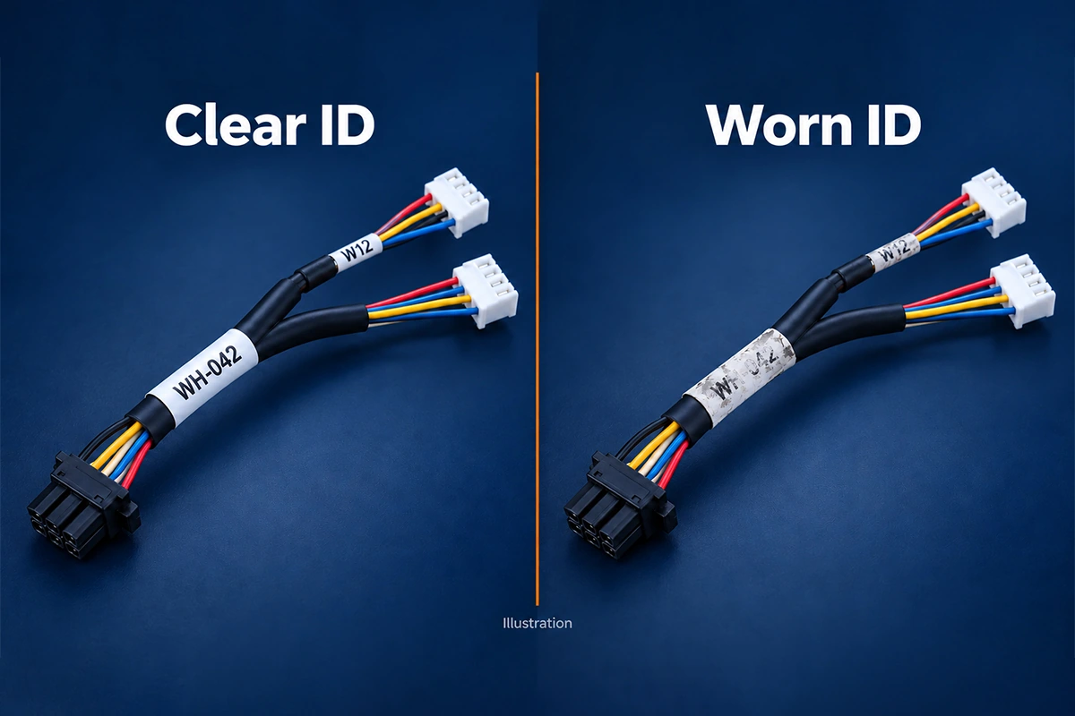
Wire harness identification labels help technicians connect the physical wiring inside a machine to its drawings, connector references, replacement parts and service records. When a label fades, peels off or becomes hidden, the harness may continue working electrically, but maintenance becomes harder. A technician must spend time establishing which branch is which before diagnosing a fault or replacing a component.
This matters in industrial equipment where similar connectors, repeated machine modules and dense wiring leave little room for guesswork. Oil, cleaning chemicals, elevated temperatures, abrasion and routine handling can damage identification long before the conductors fail.
For equipment designers and OEM buyers, the objective is therefore more specific than “add a label.” The identification must remain correct, attached, accessible and legible in the intended environment. FPIC supports project-specific marking and labeling for custom industrial harnesses, with the method selected around customer requirements rather than one universal label construction.
Three Identification Layers That Should Not Be Confused
A cable jacket legend, a harness part-number label and a wire number may sit close together, but they answer different questions.
| Identification layer | Typical information | Main purpose |
|---|---|---|
| Wire or cable manufacturer’s product marking | Manufacturer, cable designation, size, ratings and applicable certification information | Identify the wire/cable product and its permitted characteristics |
| Harness assembly identification | Assembly part number, revision, lot or serial number | Identify the manufactured assembly and connect it to the correct records |
| Equipment wiring identification | Circuit or wire number, connector ID, terminal or destination reference | Relate the installed connection to the equipment documentation |
A custom assembly label does not replace required cable markings or authorize a certification claim. Likewise, using a certified wire does not automatically certify the finished harness. UL’s Wire and Cable Application Guide distinguishes certification labeling from supplemental surface printing; the requirements depend on the wire or cable category.
IEC 62491 addresses the relationship between cable/core identification and technical documentation. Its scope excludes label physical design, label materials and cable manufacturers’ product-bound marking. It should not be presented as a label chemical-resistance specification. IEC 60204-1 concerns the electrical equipment of machines within its scope, not a blanket approval of one marker material.
Keep these layers separate when preparing drawings, purchasing specifications and inspection requirements.
What Label Deterioration Actually Costs Maintenance
An unreadable label does not necessarily create an immediate electrical fault. It removes information that a technician expects to find at the connection.
Imagine two adjacent sensor branches with the same connector housing and cable color. Their positions were clear during initial assembly. After repeated cleaning, one identifier becomes faint and the other disappears. During replacement, appearance alone no longer reliably distinguishes the branches.
The consequences can include:
- extra tracing and document checking before work begins;
- disconnecting the wrong branch during diagnosis;
- ordering a visually similar but incorrect replacement assembly;
- reconnecting a serviceable harness to the wrong equipment interface;
- losing the link between the installed part and its production history.
These are possible outcomes, not an argument that labels replace electrical verification. Technicians still need the approved service procedure and appropriate safety controls. Clear identification reduces uncertainty; it does not make trial-and-error reconnection acceptable.
A durable but incorrect label is equally problematic. Material durability and identification accuracy must be controlled together.
Keep Wire Numbers, Connector IDs and Drawings Consistent
Define what each identifier means before choosing its material. A harness part number identifies an assembly; a wire number identifies a circuit or conductor according to the equipment’s scheme; a connector reference identifies an interface. They are related, but not interchangeable.
For example, an assembly might carry part number H-204, a branch marked J3, and individual conductors identified by the approved wire list. Those references should agree with the released harness drawing, schematic, connector schedule and service information. The example is illustrative, not a prescribed numbering convention.
Specify whether each endpoint shows its own reference, its destination, or both. Mixing conventions across machine modules can create confusion even when every printed character is readable.
Useful production controls include:
- generating label data from an approved source rather than retyping it;
- checking the first printed set against the current drawing revision;
- distinguishing part numbers from lot, serial and circuit references;
- preserving leading zeros, punctuation and character case where significant;
- comparing decoded barcode data with the intended product record.
A successful scan proves that a code can be decoded. It does not prove that the code belongs to the harness carrying it.
Keep essential service information readable without a scanner when the maintenance procedure requires it. A small code can link to detailed records, but a technician may still need a short part or connector reference in poor lighting, through a restricted viewing angle, or when a database connection is unavailable. Check character size, contrast and code geometry on the finished, curved cable rather than approving only the flat artwork.
Choosing Wire Harness Identification Labels for the Job
Select the complete identification system: carrier material, adhesive or retention method, printable surface, ink or ribbon, printing process and installation condition.
| Method | Useful applications | What needs checking |
|---|---|---|
| Heat-shrink markers | Individual wires and branches where a close-fitting sleeve is suitable | Cable diameter, recovery, installation heat, print durability and assembly sequence |
| Self-laminating wrap labels | Cables requiring protected printed text | Wrap overlap, diameter range, surface compatibility and exposure limits |
| Adhesive labels or flags | Assembly identification and larger readable fields | Flexibility, adhesive suitability, snagging risk and installed visibility |
| Slide-on or clip-on markers | Wire numbers and replaceable identification systems | Fit, retention, rotation and available installation access |
| Mechanically attached tags | Larger bundles or applications unsuitable for adhesive attachment | Tag and fastener durability, movement, edges and clearance |
| Direct printing or marking | Identification without a separate carrier | Substrate compatibility, contrast, permanence and insulation integrity |
Heat shrink wire labels are not automatically the most durable option in every location. A sleeve must fit the actual wire or bundle and remain readable after recovery. It may also need to be installed before termination if it cannot pass over the completed connector.
Self-laminating designs use a clear section to cover the printed area. Brady’s B-427 data sheet illustrates this construction and also identifies specific printing and chemical-exposure conditions. Protection from an overwrap does not mean resistance to every solvent.
Polyolefin, polyester/PET, vinyl/PVC, nylon and other materials are possible candidates, but the generic polymer name is not a performance specification. Obtain the exact material grade and product data.
Thermal transfer, laser printing, inkjet and direct laser marking are different processes. Laser printing on a carrier is not the same as marking insulation directly. Any direct-marking process needs confirmation that it creates sufficient contrast without unacceptable damage.
TE’s sleeve documentation and printer/ribbon matrix demonstrate why a printable material should be qualified with its intended printing combination, rather than assumed compatible with any available printer.
Treat substitutions as changes to the identification system. Replacing the ribbon, adhesive stock or sleeve grade may affect performance even if the finished print looks identical. Keep the approved combination identifiable in the BOM or process specification, and review whether a proposed change needs new samples, supporting data or repeat exposure verification. Visual similarity alone is not evidence of equivalent durability.
Match Durability to the Actual Exposure
“Harsh environment” is too broad to support material selection. Describe what reaches the identifier, how often, at what temperature and for how long.
Oil, coolant and cleaning chemicals
Identify the actual fluids, including concentration and cleaning method. Hydraulic oil, cutting fluid, alcohol-based cleaner and other chemicals are not interchangeable exposures. A material may tolerate one while its adhesive, print coating or overlaminate responds differently to another.
Check the assembled marker, not only the base film. Oil resistance of the cable jacket does not establish oil resistance of its label.
Heat and temperature changes
Separate normal operating temperature, brief excursions and application temperature. Adhesive application limits, sleeve recovery conditions and continuous service ratings answer different questions.
Review the warmest realistic label location, including proximity to motors, drives or heated equipment. A cable’s own temperature rating is not automatically the rating of the attached identification system.
Abrasion, motion and handling
Repeated contact with a bracket, adjacent harness or operator’s gloves can wear print or lift an edge. Protecting the printed surface may help, but relocating the label away from rubbing contact is often the more useful design change.
For moving branches, assess marker stiffness and retention together with routing. A label should not create an unintended rigid transition or become a loose object that catches on nearby parts.
Moisture, sunlight and contamination
Where relevant, include condensation, washdown, outdoor UV exposure and accumulated dirt. A label that remains attached may still become difficult to read through discoloration or contamination.
Define the cleaning method that service personnel can use without removing the print or damaging insulation. Do not assume aggressive solvent cleaning is acceptable.
Label Position Is Part of the Harness Design
The best material cannot help if the identifier faces the cabinet wall or sits beneath a closed clamp.
Specify location from an identifiable feature, along with orientation where needed. Inspect it in the installed state, not only with the harness laid out on a table.
A practical placement review asks:
- Can the technician read the identifier after the harness is secured?
- Will a sleeve, conduit, clamp, connector boot or cover hide it?
- Does it interfere with a latch, sealing feature or strain-relief structure?
- Can a flag snag during installation or maintenance?
- Will rotating or lifting the label require pulling on a termination?
- Does the attachment remain secure without damaging insulation?
Avoid universal distance rules. The useful position depends on connector access, branch layout, retention points and routing space. Define a project-specific placement zone or dimension when location is important.
For long or interrupted routes, additional identification at accessible points may be useful. Repeated labels should follow the same naming convention, so they reinforce the drawing rather than introduce competing references.
Verification: Readable Today Is Not Proof of Long-Term Durability
Separate routine production inspection from qualification of a new label system.
Production checks confirm the correct material, content, position, orientation, application and initial readability. Qualification evaluates whether the selected construction remains suitable after specified exposure. A clear photograph taken at final inspection cannot establish future oil or abrasion resistance.
The following is a planning framework, not a universal test specification or a statement that every FPIC order receives every test:
| Evaluation | Conditions to define | Acceptance questions |
|---|---|---|
| Fluid exposure | Actual fluid, concentration, temperature, contact time and cleaning | Is text legible? Has the marker softened, lifted or detached? |
| Temperature exposure | Relevant temperatures, durations and cycling | Does the assembly retain readable print and suitable attachment? |
| Rub or abrasion evaluation | Contact material, force, cycles and wet/dry condition | Is the required identification still unambiguous? |
| Adhesion or retention | Actual jacket, diameter, preparation and conditioning | Does the label or sleeve remain in its specified position? |
| Barcode verification | Scanner, viewing geometry and acceptance criteria | Can the required data be read and matched correctly? |
| Installation trial | Final routing, covers, clamps and service access | Can a technician identify the connection without disturbing it? |
Use representative production samples with the intended printer settings, ribbon or ink, substrate and application method. Include surface preparation and any required adhesive dwell before exposure.
For some applications, separate tests may not capture the important failure sequence. Heat followed by oil exposure and wiping can be more representative than one isolated check. Select combined conditioning only where the specification or risk assessment justifies it.
Define pass/fail criteria before testing. “Looks acceptable” is weak if two inspectors disagree about a damaged character. Record the required text, attachment condition and machine-readability criteria. Sample count, frequency and limits should follow the agreed project plan.
Apply Standards to the Correct Identification Function
When a specification requests UL-recognized labeling, establish the relevant category and intended use. UL 969A covers specified flag labels, tags, wrap-around labels and related products on flexible electrical cords or hoses; its scope distinguishes these from labels on smooth, flat, rigid surfaces covered by UL 969. End-product requirements determine acceptability in a particular application.
UL Solutions also describes conditions of acceptability covering surfaces, temperature and exposure, with compatible printing materials controlled where applicable. A recognized label stock does not authorize arbitrary printing combinations or establish certification of the completed harness.
For OEM projects, agree on the applicable drawing, end-product requirements, customer specifications and standard editions before release. Do not treat a cable certification legend, assembly serial label and installation wire number as one compliance obligation.
How FPIC Supports Custom Industrial Identification
FPIC can customize identification for industrial equipment wire harnesses according to customer requirements, including content, marker form, material, printing or marking method and installation position.
Options can include heat-shrink sleeves, adhesive or self-laminating labels, sleeve-style markers and direct marking. The final combination requires review against the actual substrate, environment, assembly sequence and approved specification.
Our manufacturing capability covers wire processing, connector assembly, labeling, inspection and testing. Quality assurance coordinates project-related verification, while wire harness traceability links the relevant identification to manufacturing records.
Identification inspection and any environmental durability validation should be defined separately. Test methods, acceptance criteria and supporting reports are agreed for the project; they are not assumed identical across all customized assemblies.
Through our OEM/ODM services, customers can address labeling alongside the complete custom wire harness specification. Useful inputs include:
- drawing, wire list and connector identification schedule;
- required text, numbering convention and barcode format;
- actual cable jacket, diameter and installed routing;
- oil, coolant, cleaner, heat, moisture or abrasion exposure;
- required material, recognition or test documentation;
- prototype quantity, production volume and service requirements.
Plan for Replacement, Not Only Initial Assembly
Labels should support the person servicing the machine years after its original build.
During replacement, confirm the installed identity against controlled documentation before removing or reproducing a damaged marker. Preserve the distinction between the original assembly serial number and any replacement or service record. Copying an old label onto a different assembly can create a false identity.
If the identity cannot be established, follow the equipment manufacturer’s service procedure rather than guessing from color or connector shape. Replacement labels do not change pinout, ratings or configuration.
For a new project, send FPIC your harness drawing and identification requirements or email info@sz-fpi.com. Selecting the marking system during development makes its material, readability and service access part of the assembly design.
Frequently Asked Questions
Are heat-shrink markers always better than adhesive labels?
No. The suitable method depends on diameter, environment, installation access, assembly sequence and required readability. A correctly selected adhesive system may suit one location better, while a heat-shrink sleeve may be preferable elsewhere.
Does a barcode replace a printed part number?
Not necessarily. A human-readable reference can support service when scanning is unavailable. Define both formats where required, and verify that the decoded data matches the intended assembly record.
Does an oil-resistant cable need separate label verification?
Yes. The cable jacket, label carrier, adhesive and printed image have different properties. Evaluate the identification system against the actual fluid and conditions rather than relying on the cable’s oil-resistance rating.
Does IEC 62491 specify a durable label material?
No. It addresses cable/core labeling and its relationship with documentation. Label materials, physical construction and cable manufacturers’ product-bound markings are outside its scope.
Can FPIC customize wire and connector identification?
Yes. FPIC can customize marker forms, materials, content, printing or marking methods and placement according to customer requirements. The final specification and any durability verification are confirmed for the project.
Does final label inspection prove long-term readability?
No. It verifies the inspected condition at that time. Long-term suitability requires an appropriate material and printing system, installation review, and exposure testing or supporting evidence aligned with the application.
Resources
- UL Solutions — Wire and Cable Application Guide
- IEC — IEC 62491:2008, Labelling of Cables and Cores
- IEC — IEC 60204-1:2016+AMD1:2021, Electrical Equipment of Machines
- Brady — B-427 Technical Data Sheet
- TE Connectivity — TMS-SCE Technical Documents and Printer/Ribbon Matrix
- UL Standards & Engagement — UL 969A Scope
- UL Solutions — Marking and Labeling Systems Program