Why Custom Cable Assemblies Matter in Energy Storage Systems
Battery energy storage systems require more than batteries, inverters, and control electronics. They also depend on a network of power, signal, grounding, and communication connections that must operate reliably throughout the system’s service life.
Within a BESS cabinet or container, cable assemblies may connect:
- Battery cells and modules
- Battery packs and racks
- Busbars and distribution units
- Battery management systems
- Contactors, fuses, and disconnects
- Power conversion systems
- Thermal-management equipment
- Sensors and communication devices
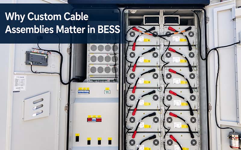
Standard off-the-shelf cables may appear suitable when voltage, current, and connector type are considered individually. In practice, however, every battery system has its own electrical architecture, cabinet dimensions, installation sequence, environmental conditions, and maintenance requirements.
A properly engineered custom cable assembly integrates these requirements into one production-ready interconnection solution.
It can improve:
- Electrical safety
- Current-carrying performance
- Temperature control
- Installation efficiency
- Polarity management
- Cabinet-space utilization
- Mechanical protection
- Maintenance accessibility
- Batch consistency
- Product traceability
For BESS manufacturers, customization is therefore not simply a matter of selecting cable length. It is a system-integration decision.
Why Interconnection Design Is Critical in a BESS
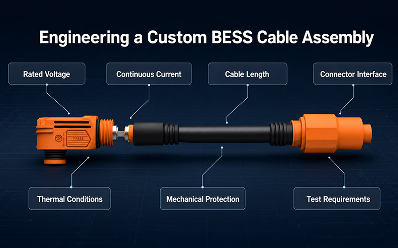
Energy storage systems combine significant electrical energy with compact mechanical packaging.
A cable assembly that performs adequately in a general industrial application may not be suitable for a battery cabinet exposed to high current, temperature cycling, vibration, restricted airflow, and repeated installation or service operations.
The interconnection system must manage several risks simultaneously.
1. Electrical Risk
Incorrect conductor sizing, high contact resistance, loose termination, or inadequate insulation may contribute to excessive voltage drop, local heating, insulation damage, or electrical failure.
2. Mechanical Risk
Poor routing, insufficient strain relief, sharp bend radii, and contact with cabinet edges may damage cables or transfer stress to terminals and connectors.
3. Installation Risk
Unclear polarity, incorrect cable lengths, inaccessible connection points, and similar-looking interfaces can increase assembly time and misconnection risk.
4. Environmental Risk
Temperature changes, humidity, dust, vibration, chemicals, and installation conditions may affect insulation, seals, connectors, and terminations.
5. Maintenance Risk
Cable assemblies that block access to modules, contactors, or service points can make inspection and component replacement slower and more hazardous.
Current IEC energy-storage standards emphasize hazard identification, risk assessment, risk mitigation, environmental conditions, and system-level safety for grid-connected electrochemical storage. These requirements apply at the complete system level, but the interconnection design contributes directly to how those safety objectives are achieved.
Standard Cables Versus Custom BESS Cable Assemblies
| Comparison Factor | Standard Cable | Custom Energy Storage Cable Assembly |
| Cable length | Fixed or limited options | Matched to cabinet routing and connection positions |
| Conductor size | Based on general product ratings | Selected according to current, voltage drop, temperature, duty cycle, and installation |
| Connector configuration | Predefined connector arrangement | Customized connector, lug, busbar, or mixed termination |
| Polarity identification | Basic color options | Color, keying, labels, and installation controls designed around the system |
| Branch structure | Usually single-point connection | Can combine multiple branches, auxiliary circuits, and sensing connections |
| Protection | General insulation or jacket | Sleeves, conduits, heat shrink, edge protection, sealing, and strain relief |
| Installation fit | May require adjustment on site | Developed for the available routing space and assembly sequence |
| Testing | Standard supplier test scope | Project-specific continuity, resistance, insulation, and withstand-voltage testing |
| Traceability | Product-level identification | Can include work order, material batch, inspection, and test records |
| Serviceability | Not optimized for the cabinet | Routing and interfaces can support inspection and module replacement |
Custom assemblies are particularly valuable when the system requires high current, compact installation, multiple cabinet variants, rapid assembly, or documented quality control.
1. Conductor Sizing Must Reflect the Real Application
Selecting a conductor only by nominal current is insufficient.
Selecting a conductor only by nominal current is insufficient.
The required cross-sectional area depends on the complete operating environment, including:
- Continuous and peak current
- System voltage
- Cable length
- Permitted voltage drop
- Ambient temperature
- Temperature inside the cabinet
- Cable bundling
- Ventilation and airflow
- Terminal and connector resistance
- Insulation temperature rating
- Installation method
- Duty cycle
- Derating requirements
A conductor that is suitable in free air may operate differently when bundled with other high-current cables inside a restricted battery cabinet.
Why Cable Resistance Matters
Conductor resistance is affected by material resistivity, cable length, and cross-sectional area. Longer cables and smaller conductors generally produce greater resistance.
As current flows through the assembly, resistance contributes to:
- Voltage drop
- Power loss
- Heat generation
The complete current path must therefore be evaluated rather than considering the cable alone.
This path includes:
- Conductor
- Crimped terminal
- Connector contact
- Bolted lug
- Busbar interface
- Mating connector
- Adjacent connection points
A larger conductor cannot compensate for a poorly designed or unstable termination.
2. High-Voltage Insulation Requires More Than a Thick Cable Jacket
BESS cable assemblies must maintain electrical isolation throughout manufacturing, installation, operation, and maintenance.
The insulation design may need to consider:
- Rated system voltage
- Working voltage
- Transient conditions
- Clearance and creepage around interfaces
- Cable insulation thickness
- Connector touch protection
- Pollution and humidity
- Altitude
- Material flammability
- Abrasion and edge contact
- Temperature exposure
- Installation bending
- Withstand-voltage requirements
High-voltage protection also depends on the connector and termination area.
A suitable design may incorporate:
- Finger-safe or touch-proof interfaces
- Insulated terminal covers
- Sealed connector housings
- Polarized mating structures
- Keying positions
- Secondary locks
- High-voltage warning identification
- Protected busbar connections
FPIC’s energy storage interconnection materials describe touch-proof structures, different keying positions, multiple connection methods, IP67 options, and connectors developed around UL 4128 requirements.
The final connector, cable, and installation configuration must still be validated against the requirements of the complete energy storage system.
3. High-Current Terminations Determine Connection Stability
A high-voltage cable assembly is only as reliable as its terminations.
Common BESS termination structures include:
- Crimped high-current contacts
- Ring terminals
- Cable lugs
- Busbar connections
- Threaded connector interfaces
- Through-hole connections
- Plug-and-receptacle systems
A reliable termination must provide:
- Low and stable contact resistance
- Sufficient mechanical retention
- Correct conductor compression
- Resistance to vibration and temperature cycling
- Protection against unintended loosening
- Suitable insulation and touch protection
- Crimping Control
High-current crimping requires a validated combination of:
- Conductor construction
- Cable size
- Terminal geometry
- Crimping equipment
- Applicator or die
- Crimp dimensions
- Pull-force requirements
- Process inspection
A crimp should not be accepted only because its external appearance appears satisfactory.
Depending on the product and agreed inspection plan, verification may include:
- Crimp-height measurement
- Crimp-width measurement
- Pull-force testing
- Cross-section analysis
- Visual inspection
- Electrical resistance testing
IPC/WHMA-A-620E defines industry requirements and acceptance criteria for cable and wire harness manufacturing, including crimped, mechanically secured, and soldered interconnections.
4. Cable Routing Affects Safety and Cabinet Integration
Routing is not a secondary packaging task. It influences electrical performance, mechanical reliability, assembly efficiency, cooling, and serviceability.
A custom BESS cable assembly can be designed around:
- Battery-module locations
- Positive and negative busbar positions
- Contactors and fuse units
- Cabinet doors and access panels
- Cooling ducts
- Sharp edges
- Moving service components
- Minimum bend radius
- Cable separation requirements
- Installation sequence
- Avoid Excessive Cable Length
Excess cable may:
- Obstruct airflow
- Create uncontrolled loops
- Increase voltage drop
- Interfere with components
- Complicate maintenance
- Increase material use
- Make polarity identification more difficult
- Avoid Insufficient Cable Length
A cable that is too short may:
- Pull against the connector
- Transfer stress to the crimp
- Reduce bend-radius compliance
- Make installation difficult
- Prevent convenient module replacement
- Create mechanical loading after thermal expansion
- Protect Cables from Cabinet Edges
Routing near metal frames may require:
- Grommets
- Edge guards
- Conduits
- Braided sleeves
- Corrugated tubing
- Heat-shrink protection
- Clamps and fixing points
The protective material must be selected according to abrasion, temperature, flame, chemical, and installation requirements.
5. Polarity Management Helps Prevent Installation Errors
Polarity errors in energy storage applications can have severe consequences.
A customized connection system can reduce risk through several coordinated controls.
Color Identification
Positive and negative circuits can use clearly defined cable, housing, heat-shrink, or label colors.
Mechanical Keying
Different keying positions can prevent positive and negative connectors from being interchanged.
Connector Coding
Mating interfaces can use distinct shapes, installation positions, or locking structures.
Permanent Labels
Cable labels may identify:
- Positive or negative polarity
- Connection point
- Battery rack
- Module number
- Circuit number
- Installation direction
- Product and batch information
- Controlled Cable Lengths
Different routing lengths may help ensure that each cable naturally reaches only the intended connection point.
No single control should be relied upon in isolation. The most reliable approach combines visual identification, mechanical prevention, assembly instructions, and electrical verification.
6. Connectors Must Support Safe and Efficient Installation
A BESS connector affects more than current transmission.
Its structure influences:
- Assembly speed
- Available cabinet space
- Mating confirmation
- Touch safety
- Maintenance access
- Misconnection prevention
- Cable exit direction
- Sealing
- Field replacement
Useful design features may include:
- Tool-free or controlled release
- 360-degree cable orientation
- Distinct keying positions
- Compact right-angle configurations
- Touch-proof contacts
- Secondary locking
- Sealed interfaces
- Clear polarity identification
- Busbar-compatible receptacles
FPIC’s energy storage portfolio includes customized connector and cable configurations with different pole orientations and multiple busbar or cable connection methods.
Connector selection must be based on the actual cable size, current requirement, installation space, mating cycles, sealing level, and system certification plan.
7. Signal and Communication Assemblies Also Matter
High-voltage power cables are only one part of an energy storage wiring system.
BESS equipment may also use low-voltage harnesses for:
- Battery voltage sensing
- Temperature sensing
- Current sensing
- Battery management communication
- Contactor control
- Fan and pump control
- Interlock circuits
- Smoke and environmental monitoring
- CAN or other communication protocols
These assemblies may require different engineering priorities from power cables, such as:
- Signal integrity
- Shielding
- Twisted pairs
- Separation from power circuits
- Small-gauge terminal reliability
- Connector cavity accuracy
- Electromagnetic interference control
A custom manufacturer can coordinate power and signal assemblies under one project documentation structure while applying appropriate materials and test methods to each circuit type.
8. Serviceability Should Be Considered During Design
Energy storage systems may require module inspection, maintenance, or component replacement during their operating life.
Poorly designed cable assemblies can make these activities slower and more hazardous.
A service-oriented design should consider:
- Whether a cable blocks module removal
- Whether connectors can be accessed safely
- Whether polarity remains clear after disconnection
- Whether cables can be replaced individually
- Whether tools can reach bolted connections
- Whether strain relief remains effective after maintenance
- Whether routing can be restored correctly
- Whether cable labels remain readable
Useful serviceability features may include:
- Modular cable sections
- Clearly differentiated connectors
- Controlled connector release
- Replaceable plug-in assemblies
- Defined fixing points
- Permanent circuit identification
- Installation drawings
- Cable routing documentation
Designing for serviceability can reduce maintenance time and lower the risk of incorrect reassembly.
9. Customization Supports Different BESS Architectures
Energy storage systems vary significantly in layout and capacity.
Residential Energy Storage
These systems often prioritize:
- Compact size
- Safe touch protection
- Simple installation
- Clean cable routing
- Low maintenance
- Controlled connector access
Commercial and Industrial Systems
These applications may require:
- Modular battery racks
- Higher current capacity
- Multiple cabinet variants
- Fast field installation
- Flexible power distribution
- Detailed traceability
Containerized Utility-Scale BESS
Large systems may introduce:
- Longer cable routes
- Multiple battery racks
- High fault-energy considerations
- Complex thermal-management systems
- Outdoor environmental exposure
- Service and replacement requirements
- Strict project documentation
Rack-Level and Module-Level Assemblies
Different interconnection layers may require:
- Module jumpers
- Rack power cables
- Rack-to-distribution cables
- Grounding assemblies
- BMS signal harnesses
- Auxiliary power wiring
Custom cable assemblies allow the electrical and mechanical configuration to be aligned with each architecture rather than forcing one standard cable into every installation.
10. Testing Must Match the Cable’s Function
Testing requirements should be defined during engineering review and included in the production documentation.
Continuity Testing
Confirms that the intended circuit is complete.
Open-Circuit Detection
Identifies disconnected conductors, incomplete crimps, or improperly seated contacts.
Short-Circuit Testing
Detects unintended connections between circuits.
Miswiring Verification
Confirms that each conductor reaches the correct connection point.
Insulation Resistance Testing
Evaluates electrical isolation between conductors or between the circuit and shield or housing.
Withstand-Voltage Testing
Checks insulation integrity under a specified test voltage and duration when required.
Resistance Measurement
High-current assemblies may require low-resistance or milliohm measurement to evaluate connection performance.
Mechanical Testing
Depending on the project, this may include:
- Pull-force testing
- Connector insertion and withdrawal force
- Vibration
- Cable bending
- Drop or transportation testing
Environmental Testing
Possible validation includes:
- Temperature cycling
- Thermal shock
- Temperature rise
- Humidity
- Salt spray
- Flammability
- Ingress protection
FPIC’s documented test resources include contact-resistance, temperature-rise, cable-harness, withstand-voltage and insulation testers, along with thermal-shock, humidity, vibration, wire-bending, flammability, and dimensional inspection equipment.
The exact test plan should be agreed according to the cable assembly’s application, risk level, customer specification, and relevant standard.
11. First-Article Confirmation Reduces Batch Risk
Custom cable assemblies often combine project-specific materials, dimensions, tooling, and testing requirements.
Before batch production begins, the first completed assembly should be evaluated against the released documentation.
A first-article check may include:
Material Verification
- Cable part number
- Conductor size
- Connector and terminal
- Seal and housing
- Protective materials
- Labels and accessories
Dimensional Verification
- Overall cable length
- Branch length
- Strip length
- Lug orientation
- Connector exit direction
- Heat-shrink position
- Label location
Termination Verification
- Crimp dimensions
- Pull force
- Terminal position
- Conductor condition
- Insulation support
- Bolt or threaded interface requirements
Electrical Verification
- Circuit continuity
- Correct polarity
- Resistance
- Insulation
- Withstand voltage where required
Only after approval should the process be released for continuous production.
This prevents an incorrect setup from being repeated throughout the order.
12. Traceability Strengthens Quality Control
BESS customers may require objective manufacturing records rather than only a final inspection label.
A traceable cable assembly record can include:
- Customer part number
- Manufacturer part number
- Drawing revision
- Work order
- Cable batch
- Terminal and connector batches
- Crimping equipment
- Tooling identification
- Operator
- First-article approval
- Inspection results
- Electrical test results
- Failure and retest records
- Packaging and shipment batch
When connected with PLM, ERP, WMS, MES, and quality systems, these records help support:
- Engineering-change control
- Material traceability
- Process verification
- Root-cause analysis
- Corrective action
- Customer documentation
- Repeat-order consistency
Traceability is especially valuable when similar cable assemblies are produced for multiple cabinet versions or international projects.
From Engineering Requirements to Mass Production
A reliable custom energy storage cable project should follow a controlled development sequence.
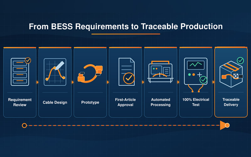
1. Requirement Review
The manufacturer reviews:
- System voltage
- Continuous and peak current
- Connection points
- Installation environment
- Routing space
- Cable length
- Connector requirements
- Applicable standards
- Testing and documentation
2. Design and Material Selection
The engineering team defines:
- Conductor size
- Cable construction
- Insulation and jacket
- Connector or terminal
- Protection materials
- Routing and bend requirements
- Labeling and polarity controls
3. Prototype Development
Samples are produced to verify:
- Dimensional fit
- Assembly method
- Connector accessibility
- Routing
- Termination quality
- Electrical performance
4. First-Article Approval
The initial production assembly is checked against the approved design and process requirements.
5. Controlled Production
Validated equipment, tooling, work instructions, and process parameters are used for batch manufacturing.
6. Electrical and Quality Testing
Finished products are tested according to the agreed inspection plan.
7. Packaging and Traceability
Cable ends, connectors, labels, and routing geometry are protected during shipment, while manufacturing records are retained.
What Information Should Customers Provide?
To evaluate a custom BESS cable assembly, customers should provide as much of the following information as possible:
| Information Category | Required Details |
| Technical files | 2D/3D drawings, wiring diagrams, BOM, wire list, or samples |
| Application | Residential, commercial, industrial, rack-level, cabinet-level, or containerized BESS |
| Electrical data | Rated voltage, continuous current, peak current, and test requirements |
| Connection points | Battery module, rack, busbar, contactor, fuse, PCS, or distribution unit |
| Cable requirements | Conductor size, insulation, jacket, flexibility, color, and length |
| Connector requirements | Interface type, keying, locking, sealing, orientation, and mating cycles |
| Environment | Temperature, humidity, indoor/outdoor use, vibration, chemicals, and altitude |
| Mechanical requirements | Routing space, bend radius, fixing points, strain relief, and edge protection |
| Compliance | Customer standards, regional requirements, RoHS, REACH, UL, IEC, or other specifications |
| Commercial information | Prototype quantity, annual demand, delivery schedule, and target production location |
Where information is incomplete, engineering clarification should occur before tooling or mass production.
FPIC Custom Cable Assemblies for Energy Storage Systems
FPIC provides customized connector and cable assembly solutions for battery modules, battery racks, cabinets, and related energy storage equipment.
High-Voltage and High-Current Assemblies
FPIC supports custom power cables with application-specific conductor sizes, connector interfaces, terminal configurations, cable lengths, protection materials, and polarity identification.
Energy Storage Connectors and Cables
Available design features can include:
- Touch-proof connection structures
- Positive and negative identification
- Different mechanical keying positions
- Rotatable cable exits
- Busbar-compatible receptacles
- Sealed connection options
- Custom cable lengths
- Multiple installation methods
Automated Processing
FPIC’s documented manufacturing resources include wire-cutting and stripping equipment, servo crimping machines, integrated wire-processing equipment, housing-insertion capabilities, and electrical test systems.
First-Article Confirmation
Material, dimensional, termination, appearance, and electrical requirements are verified before batch production proceeds.
100% Electrical Testing
Finished cable assemblies can be tested for circuit accuracy and specified electrical requirements before shipment.
Digital Manufacturing Management
PLM, ERP, MES, WMS, QMS, SCADA, and related systems support engineering-data control, material management, production execution, testing, and traceability.
End-to-End Customization
FPIC supports customers through:
Requirement Review → Engineering Design → Material Selection → Prototype → Validation → First Article → Batch Production → Testing → Traceable Delivery
Why Customers Choose FPIC
Application-Oriented Engineering
Each project is evaluated according to its actual voltage, current, routing, environment, and assembly requirements.
Connector and Cable Integration
FPIC develops both connectors and cable assemblies, helping coordinate conductor, contact, housing, sealing, routing, and termination requirements.
Automated Manufacturing
Suitable processing stages are automated to improve dimensional consistency, termination stability, production capacity, and batch repeatability.
Quality and Testing Resources
FPIC operates quality and manufacturing systems that support customized industrial and energy storage interconnection products.
Scalable Production
The manufacturing process can support progression from prototype evaluation to repeat batch production.
Zero-Risk Development Support
For qualified custom development projects, FPIC can offer a zero-risk development commitment based on mutually agreed project requirements.
Conclusion
Custom cable assemblies are essential components in reliable battery energy storage systems.
Their role extends far beyond carrying electrical current. A properly developed assembly coordinates conductor size, insulation, connector selection, polarity, routing, strain relief, environmental protection, installation, testing, and maintenance.
Compared with a standard cable, a project-specific solution can provide:
- Safer high-voltage connections
- More stable high-current performance
- Better cabinet-space utilization
- Faster and more accurate installation
- Improved mechanical protection
- Easier maintenance
- More consistent batch production
- Stronger test and traceability records
The most effective approach is to involve the cable assembly manufacturer early in the BESS development process.
Early engineering collaboration allows electrical requirements, cabinet layout, connector interfaces, production feasibility, and test methods to be evaluated before the design is fixed.
For BESS manufacturers, this can reduce integration risks and establish a more controlled path from prototype development to scalable mass production.
FAQ
1. Why are custom cable assemblies important in energy storage systems?
They align electrical ratings, conductor size, connector interfaces, cable lengths, routing, protection, testing, and installation requirements with the actual BESS architecture.
2. What cables are used in a battery energy storage system?
A BESS may use high-voltage power cables, module and rack connections, grounding assemblies, BMS signal harnesses, sensor cables, interlock wiring, and communication cables.
3. How should conductor size be selected for a BESS cable?
Selection should consider continuous and peak current, voltage drop, cable length, ambient temperature, bundling, ventilation, duty cycle, connection resistance, and applicable derating requirements.
4. What is the difference between a standard cable and a custom energy storage cable assembly?
A standard cable provides predefined lengths and terminations. A customized assembly is engineered around the system’s electrical architecture, cabinet layout, connector interfaces, environmental conditions, installation process, and test requirements.
5. Why is connector keying important?
Mechanical keying helps prevent incompatible interfaces or positive and negative connections from being incorrectly mated.
6. Do high-voltage cable assemblies require 100% testing?
The test scope depends on the agreed specification, but finished products should normally be verified for circuit accuracy and applicable electrical requirements before shipment.
7. What tests are used for energy storage cable assemblies?
Testing may include continuity, miswiring, resistance, insulation resistance, withstand voltage, pull force, temperature rise, vibration, thermal cycling, and environmental testing.
8. What is first-article confirmation?
It is the verification of the initial production assembly’s materials, dimensions, terminations, configuration, workmanship, and electrical performance before batch production begins.
9. Can FPIC customize both connectors and cables?
Yes. FPIC can evaluate connector interfaces, cable construction, terminals, cable length, routing, protection, labeling, and testing as one customized interconnection solution.
Develop a Safer and More Reliable BESS Connection
FPIC supports custom energy storage cable assemblies from requirement review and prototype development through automated processing, first-article confirmation, 100% electrical testing, and traceable batch production.
Send us your drawings, wiring diagram, BOM, rated voltage and current, connector requirements, installation layout, test specifications, and expected annual volume.
Email: info@sz-fpi.com
Resources
- IEC 62933-5-1:2024 — General Safety Considerations for Grid-Integrated Electrical Energy Storage Systems
Defines hazard identification, risk assessment, and risk-mitigation considerations applicable to grid-connected energy storage systems. - IEC 62933-5-2:2025 — Safety Requirements for Electrochemical Energy Storage Systems
Provides additional safety provisions associated with electrochemical storage subsystems used in grid-connected energy storage systems. - IEC 62933-4-3:2025 — Environmental Protection Requirements for BESS
Addresses protection requirements associated with environmental conditions affecting battery energy storage systems. - IPC/WHMA-A-620E — Cable and Wire Harness Assembly Requirements
Covers manufacturing practices, materials, test methods, and acceptance criteria for crimped, mechanically secured, and soldered cable and harness assemblies. - UL Solutions — Energy Storage System Safety and Certification
Provides an overview of safety standards and certification considerations for energy storage systems and equipment, including UL 9540 and UL 9540A.