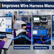
How Digital Work Instructions Improve Wire Harness Quality
Digital work instructions provide production operators with controlled, step-by-step assembly information generated from approved engineering data.
In wire harness manufacturing, they can display wire numbers, connector cavities, terminal specifications, stripping dimensions, crimping requirements, branch locations, protective materials, inspection points, and test procedures directly at the workstation.
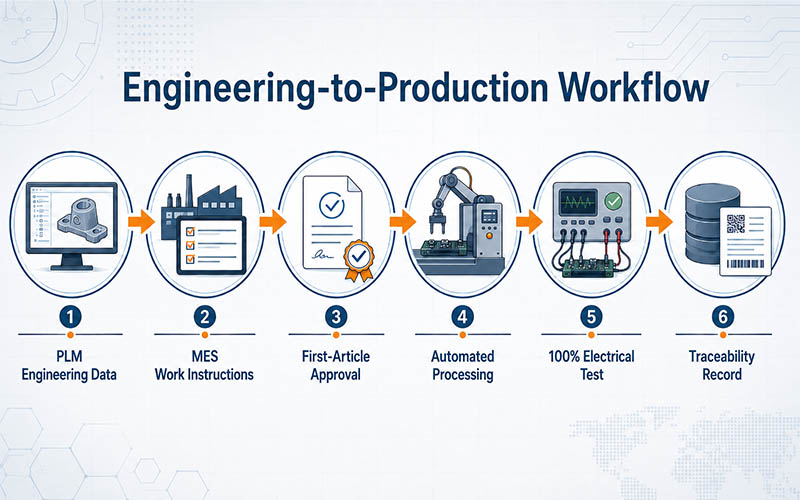
When connected with PLM, ERP, MES, and electrical test systems, digital instructions help create a closed manufacturing workflow:
Engineering Data → Production Instructions → First-Article Approval → Assembly → Electrical Testing → Quality Records → Product Traceability
This approach reduces dependence on paper drawings, limits manual data entry, and helps manufacturers maintain consistent production requirements across prototypes, engineering changes, and mass-production batches.
Zuken’s 2026 manufacturing updates reflect this direction. Its latest Harness Builder solution strengthens bill of materials and wire-list reporting, introduces digital assembly task management, and supports direct connections with Cirris and Weetech harness testers.
Why Paper-Based Assembly Instructions Create Manufacturing Risk
Wire harnesses often combine many individual production variables:
- Wire type, color, gauge, and length
- Terminal and seal combinations
- Connector cavity assignments
- Strip lengths and crimp parameters
- Branch dimensions and routing direction
- Sleeves, conduits, tapes, labels, and ties
- Shielding and grounding structures
- Electrical test requirements
- Customer-specific workmanship criteria
In a paper-based workflow, engineering drawings, bills of materials, wire lists, process cards, and test tables may be printed and distributed separately.
This creates several potential problems.
1. Outdated Documents on the Production Floor
After an engineering change, previously printed drawings may remain at workstations. Unless every obsolete copy is identified and removed, an operator may continue working to an outdated revision.
2. Manual Transcription Errors
Production personnel may need to manually transfer wire data from engineering documents into cutting machines, crimping equipment, labels, or test programs. Each manual entry creates another opportunity for an incorrect part number, wire length, cavity position, or test point.
3. Inconsistent Interpretation
Complex harness drawings may be understood differently by different operators, particularly when products contain multiple branches, similar connectors, optional circuits, or customer-specific variants.
4. Incomplete Quality Records
Paper inspection sheets can confirm that a process was checked, but they may not automatically associate the result with the exact work order, material batch, operator, machine, test program, and product serial number.
Digital work instructions address these risks by giving the operator controlled information from one approved data source.
What Are Digital Work Instructions?
Digital work instructions are interactive production documents displayed through a computer, industrial screen, tablet, or workstation terminal.
Unlike a scanned PDF, a structured digital instruction can guide the operator through the manufacturing sequence one operation at a time.
Depending on the product and system configuration, the interface may include:
- Product number and drawing revision
- Customer and project information
- BOM and approved component specifications
- Wire-list data
- Connector cavity diagrams
- Wire routing and branch dimensions
- Strip and crimp dimensions
- Tooling or applicator requirements
- Process images or short videos
- Inspection checkpoints
- First-article approval status
- Test program and acceptance criteria
- Nonconformance reporting instructions
The system can also require confirmation before the operator proceeds to the next stage.
This is particularly valuable for high-mix, low-volume production, where the factory frequently switches between different customized cable assemblies.
From Engineering Data to Controlled Production
The main value of digital manufacturing is not simply replacing paper with a screen. It is maintaining the integrity of engineering data as the product moves into production.
1. Engineering Data Creation
The process begins with approved product information, including:
- Customer drawings
- Electrical schematics
- Connector and terminal specifications
- Wire and cable requirements
- BOM data
- Wire lists
- Assembly dimensions
- Testing requirements
Engineering teams review whether the proposed construction is suitable for manufacturing, installation, electrical loading, mechanical stress, and the intended operating environment.
2. Controlled BOM and Wire-List Management
The BOM identifies the approved materials for the assembly, while the wire list defines the individual electrical connections.
A structured wire list commonly includes:
- Circuit identification
- From and to connection points
- Connector cavity numbers
- Wire specification
- Wire gauge
- Wire color
- Cut length
- Terminal part numbers
- Seals and accessories
- Processing notes
Zuken’s 2026 update includes customer-specific report profiles for BOM and wire-list reports, improved handling of harness variants, and manufacturing outputs intended to reduce repeated manual preparation.
This is important because many cable manufacturers serve customers with different reporting formats, part-number conventions, labeling rules, and quality documentation requirements.
3. Digital Release to Production
After engineering approval, the correct product revision can be released through PLM or another controlled document system.
The manufacturing system should then ensure that:
- Only the approved revision is available
- Obsolete instructions are blocked
- The correct process route is assigned
- Required tools and machines are identified
- Inspection and testing requirements are included
- Engineering changes are recorded
This creates a more reliable transition from design to manufacturing.
How Digital Instructions Support Each Production Stage
1. Incoming Material Verification
Before production begins, material information can be checked against the approved BOM.
Verification may include:
- Wire and cable part number
- Connector and housing model
- Terminal specification
- Seal and accessory type
- Material batch
- Supplier lot
- Compliance documentation
- Storage and shelf-life requirements
Barcode or QR-code scanning can help confirm that the selected material matches the current work order.
2. Wire Cutting and Stripping
The workstation can provide or transmit:
- Wire part number
- Required cut length
- Strip length
- Quantity
- Tolerance
- Marking or label data
- Equipment program number
This reduces the need to re-enter information from a printed wire list.
3. Terminal Crimping
Crimping instructions may include:
- Terminal part number
- Applicable wire range
- Applicator or tooling number
- Crimp height
- Crimp width
- Pull-force requirement
- Seal position
- Visual acceptance examples
Where equipment integration is available, production parameters and results can be linked to the manufacturing order.
4. Connector Insertion
Digital cavity diagrams help operators identify:
- Connector orientation
- Pin or cavity number
- Circuit identification
- Wire color
- Secondary-locking requirements
- Seal or plug locations
For connectors with similar cavity layouts, clear digital visualization can reduce mis-insertion risk.
5. Routing and Branch Assembly
Harness boards or digital assembly stations can guide:
- Main-trunk routing
- Branch direction
- Breakout position
- Tie and tape locations
- Sleeve or conduit length
- Label position
- Bend-radius requirements
- Grounding and shielding termination
- Final Inspection and Electrical Testing
The completed product can then move into visual, dimensional, and electrical verification using the test requirements associated with the current revision.
First-Article Confirmation Before Batch Production
First-article confirmation is a critical control point between production setup and volume manufacturing.
Its purpose is to verify that the initial product made under the released process meets the approved engineering requirements before the remaining batch is produced.
A complete first-article review may cover:
1. Material Verification
Confirm that the wires, terminals, connectors, seals, protective materials, labels, and accessories match the released BOM.
2. Processing Verification
Check:
- Wire length
- Strip length
- Crimp condition
- Terminal position
- Seal installation
- Soldering quality, where applicable
- Heat-shrink position
- Overmolding or low-pressure molding quality
- Assembly Verification
Confirm:
- Connector cavity assignment
- Branch dimensions
- Routing direction
- Tape and sleeve position
- Label content
- Mechanical protection
- Overall product appearance
3. Electrical Verification
Perform the required continuity, short-circuit, miswiring, insulation, and withstand-voltage tests.
4. Digital Approval
The first-article result should be linked to:
- Work-order number
- Product number
- Drawing revision
- Material batch
- Machine or workstation
- Operator
- Inspector
- Test program
- Approval time
After approval, MES can release the batch for continued production. When the first article fails, the system can prevent unauthorized continuation until the issue is reviewed.
Direct Connection Between Design Data and Test Equipment
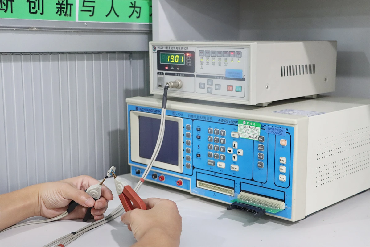
Electrical testing is one of the most important quality controls in cable assembly production.
Traditional test preparation may require a technician to manually create a test program from a drawing or wire table. For a complex harness, this can require extensive data entry and independent verification.
Direct data integration allows approved connection information to be transferred into supported test systems.
Zuken states that its 2026 Harness Builder solution supports direct integration with Cirris and Weetech testers, helping streamline the transition from wire-harness design data to production testing.
Earlier Harness Builder developments also emphasized generating manufacturing documentation and tester outputs directly from design information rather than recreating them manually.
A connected testing workflow can reduce:
- Manual test-program creation
- Incorrect test-point entry
- Duplicate data maintenance
- Revision mismatches
- Time required for new-product setup
However, direct integration does not eliminate process validation. The test fixture, mating adapters, program logic, and acceptance limits should still be verified before production release.
What Should 100% Electrical Testing Cover?
The test scope depends on the application and product specification.
Continuity Test
Confirms that each required circuit has a complete electrical path.
Open-Circuit Test
Identifies missing contacts, incomplete crimping, damaged conductors, or disconnected circuits.
Short-Circuit Test
Detects unintended electrical connections between circuits.
Miswiring Test
Confirms that every conductor is inserted into the correct connector cavity.
Insulation Resistance Test
Evaluates whether electrical isolation between conductors or between conductor and shield meets the specified requirement.
Withstand-Voltage Test
Applies a defined voltage for a specified period to verify insulation integrity when required by the product standard or customer specification.
Resistance or Milliohm Test
For selected power or low-resistance circuits, resistance measurement may be needed to evaluate conductor and connection performance.
Testing requirements should be defined during engineering review rather than added only after the product reaches the factory floor.
Test Record Management and Product Traceability
Passing the test is only one part of the quality process. The result also needs to be retained and associated with the correct product and manufacturing batch.
A useful test record may include:
- Product number
- Product serial number or batch number
- Work order
- Drawing revision
- Test-program revision
- Test fixture
- Test equipment identification
- Test date and time
- Operator or technician
- Measured result
- Pass or fail status
- Retest history
- Failure code
- Corrective-action reference
When test equipment is linked with MES or a quality database, records can be automatically associated with the production order.
This supports faster investigation when a customer reports a field issue or requests manufacturing evidence.
MES Traceability in Wire Harness Production
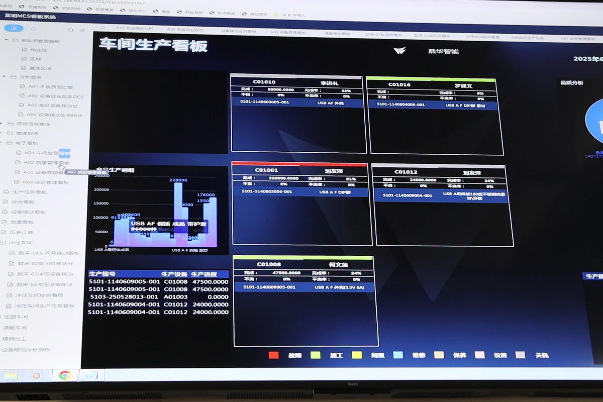
MES connects work instructions, production status, inspection records, and equipment data at the execution level.
For customized wire harness manufacturing, MES can support:
1. Production Order Control
The system identifies what product is being made, in what quantity, and to which revision.
2. Process Routing
Each product follows its assigned operations, such as:
Cutting → Stripping → Crimping → Subassembly → Connector Insertion → Routing → Inspection → Electrical Test → Packaging
3. Operator Authorization
Only trained or authorized personnel can perform designated operations where required.
4. Material Traceability
Materials and batches can be scanned and associated with the order.
5. Process Confirmation
Operators confirm completion of required steps, while inspectors record results at defined control points.
6. Nonconformance Control
Failures can be recorded with defect categories, dispositions, and corrective actions.
7. Test Record Collection
Electrical test results can be stored against the specific order, batch, or serial number.
8. Production Status Visibility
Manufacturing and management teams can see whether an order is awaiting materials, in production, under inspection, being reworked, or completed.
MES therefore acts as the operational connection between engineering requirements and actual production records.
How ERP, PLM, MES, WMS, and QMS Work Together
A mature digital manufacturing environment normally uses several systems rather than expecting one platform to manage every activity.
| Digital System | Primary Role in Wire Harness Manufacturing |
| PLM | Controls product data, drawings, BOMs, specifications, and engineering revisions |
| ERP | Manages orders, purchasing, planning, costing, and overall business resources |
| WMS | Controls material location, lot information, inventory movement, and FIFO management |
| MES | Executes production orders, distributes work instructions, and records process results |
| QMS | Manages inspections, nonconformities, corrective actions, and quality records |
| SCADA | Collects or visualizes operating data from connected production equipment |
| BI | Converts operational data into performance and management analysis |
The real benefit appears when these systems share controlled information.
For example:
- PLM releases an approved product revision.
- ERP creates or schedules the production order.
- WMS prepares the correct material batches.
- MES sends the current instruction to each workstation.
- Production equipment processes the product.
- Inspection and test systems record results.
- QMS manages any nonconformance.
- BI analyzes yield, defects, capacity, and delivery performance.
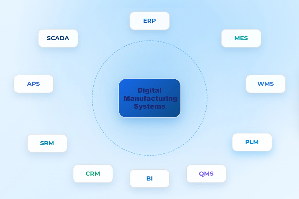
FPIC’s company materials identify PLM, ERP, MES, WMS, QMS, SCADA, BI, CRM, and other digital platforms as part of its intelligent manufacturing management environment.
Benefits for Custom Wire Harness Customers
1. Lower Risk of Revision Errors
Operators receive the current approved production information rather than relying on uncontrolled paper copies.
2. Faster New-Product Introduction
Structured engineering data can be reused for work instructions, reports, machine setup, inspection, and testing.
3. Improved First-Pass Yield
Clear assembly guidance and in-process verification can identify errors before they reach final inspection.
4. More Consistent Quality
Standardized instructions reduce differences between operators, shifts, and production batches.
5. Faster Engineering Change Implementation
Revised information can be released through the digital system without manually replacing multiple sets of paperwork.
6. Stronger Production Traceability
Materials, operations, inspections, and test records can be linked to the relevant order or product.
7. Better Support for High-Mix Production
The system can quickly load the correct instructions when the factory changes from one customized assembly to another.
8. More Transparent Supplier Evaluation
Customers can evaluate not only whether a factory owns equipment, but also how it controls product data, revisions, test records, and manufacturing evidence.
FPIC’s Digital Wire Harness Manufacturing System
FPIC combines engineering support, wire harness production, quality control, and digital manufacturing management for customized projects.
Its manufacturing resources include a dedicated wire harness workshop as well as automatic assembly and inspection capabilities. Company documentation lists wire cutting and stripping equipment, servo crimping machines, line-sequence testing, terminal-processing equipment, and integrated wire cutting, stripping, crimping, and tin-dipping machinery.
FPIC’s earlier wire harness materials also document automatic wire cutting and terminal crimping, automatic housing insertion, visual inspection, alignment checking, and product electrical testing.
Engineering Data Management
PLM supports the control of product drawings, BOMs, technical documentation, and engineering revisions before information is released to production.
Production Execution
MES helps link manufacturing orders with process routing, workstation instructions, operator activities, inspection status, and production records.
Material Control
ERP and WMS support production planning, material preparation, inventory management, and lot traceability.
First-Article Confirmation
Before batch production, the initial assembly can be checked against approved material, dimensional, process, appearance, and electrical requirements.
100% Electrical Testing
Completed assemblies can be verified for continuity, open circuits, short circuits, and wiring correctness, with additional tests performed according to the agreed specification.
FPIC’s equipment list includes cable-harness testers and withstand-voltage and insulation test equipment, supporting electrical verification for customized assemblies.
Test Record Management
Test and inspection results can be retained as part of the manufacturing quality record, helping support traceability, failure analysis, and customer documentation requirements.
Digitalization Does Not Replace Manufacturing Expertise
Digital instructions can prevent many information-related mistakes, but they cannot compensate for an unsuitable product design or an uncontrolled manufacturing process.
Reliable wire harness production still requires engineering judgment in areas such as:
- Connector and terminal compatibility
- Conductor sizing
- Current-carrying capacity
- Voltage and insulation requirements
- Crimp design and process capability
- Shield termination
- Bend radius
- Dynamic flexing
- Vibration resistance
- Temperature exposure
- Chemical resistance
- Sealing and ingress protection
- Assembly accessibility
- Serviceability
Digital manufacturing is most effective when accurate engineering data, validated processes, capable equipment, trained operators, and disciplined quality control operate as one system.
Building a Closed-Loop Manufacturing Process
A reliable digital workflow should not end when a work instruction appears on a screen.
The system should create a feedback loop:
Design Requirements → Manufacturing Instructions → Production Results → Test Data → Quality Analysis → Engineering Improvement
For example, repeated crimp-height variation may indicate:
- Tool wear
- Incorrect terminal or wire combination
- Setup inconsistency
- Material variation
- Equipment maintenance requirements
Repeated continuity failures at one connector cavity may reveal:
- An unclear cavity diagram
- Similar wire colors
- Insufficient terminal retention
- Routing stress
- A fixture or test-adapter issue
When production and quality data are structured, manufacturers can identify recurring patterns and improve both the process and the product design.
This is where digitalization begins to deliver more than paper reduction. It becomes a tool for continuous manufacturing improvement.
The Future of Wire Harness Manufacturing
Digital work instructions, automated wire processing, connected test equipment, and manufacturing traceability are becoming important capabilities for modern cable assembly suppliers.
The next stage of development is likely to include:
- More direct engineering-to-machine data transfer
- Automated revision control across workstations
- Real-time crimp and process monitoring
- Digital first-article approval
- Automatic test-result collection
- Electronic product history records
- AI-assisted defect analysis
- Predictive maintenance for production equipment
- Data-based process optimization
For buyers, the most important question will no longer be only:
“Can this supplier manufacture the harness?”
It will also be:
“Can this supplier control engineering data, production instructions, materials, inspections, tests, and revisions throughout the complete manufacturing process?”
Conclusion
Digital work instructions are transforming how custom wire harnesses move from engineering into production.
By replacing disconnected paper documents and repeated manual data entry with controlled digital information, manufacturers can improve revision management, assembly clarity, first-article confirmation, electrical testing, and product traceability.
The strongest manufacturing model connects:
- PLM-controlled engineering data
- ERP production planning
- WMS material management
- MES execution and traceability
- Digital workstation instructions
- First-article approval
- 100% electrical testing
- Structured inspection and test records
FPIC is developing this integrated approach to support customers who require reliable industrial equipment harnesses, medical cable assemblies, new-energy interconnection products, and other customized wiring solutions.
FAQ
1. What are digital work instructions in wire harness manufacturing?
They are controlled electronic assembly instructions generated from approved engineering data and displayed at production workstations.
2. How do digital instructions reduce wiring errors?
They provide operators with current wire, terminal, cavity, routing, assembly, and inspection information without relying on manually interpreted or outdated paper documents.
3. What is the role of MES in cable assembly production?
MES distributes production requirements, controls process routing, records operator and inspection activities, and links manufacturing information with the relevant work order or product.
4. Why is first-article confirmation necessary?
It verifies that materials, processing parameters, dimensions, assembly, appearance, and electrical performance meet requirements before the full batch is produced.
5. Can wire harness design data connect directly to test equipment?
Supported engineering and manufacturing software can export connection data to compatible testers, reducing manual test-program entry while still requiring program and fixture validation.
6. What information should a wire harness test record contain?
It should identify the product, revision, batch or serial number, tester, program, fixture, operator, test time, result, and any failure or retest history.
7. Does digital manufacturing eliminate manual assembly?
No. Many complex harnesses still require skilled manual work, but digital guidance and connected quality controls make those operations more standardized and traceable.
8. Why is 100% electrical testing important?
It confirms that each completed product meets the specified continuity, circuit assignment, isolation, and electrical safety requirements before shipment.
Connect Engineering Data with Reliable Production
FPIC supports customized wire harness projects from requirement review and prototype validation through controlled production, first-article confirmation, 100% electrical testing, and batch traceability.
Share your drawings, BOM, wire list, samples, application requirements, and expected annual volume with our engineering team.
Email: info@sz-fpi.com
Resources
- Zuken — What’s New in 2026 for Wire Harness Manufacturing with E3.series
Zuken’s 2026 manufacturing update introduces enhanced BOM and wire-list reporting, Assembly Task Manager digital instructions, and direct Cirris and Weetech tester integration. - Zuken — Harness Builder Design-to-Manufacturing Development
Earlier Harness Builder updates explain how manufacturing reports and test-system data can be generated from engineering information to reduce duplicate data entry and rework.