Why Crimp Tooling Matters in Wire Harness Quality
A reliable crimp is not created by press force alone. It results from a controlled system in which the terminal, wire, applicator, press, setup parameters, inspection method, and maintenance status all work together. If the applicator does not match the terminal and conductor combination, even an automated machine can repeatedly produce an unstable connection.
For OEM engineers and procurement teams, wire harness crimping quality depends on far more than a production accessory. Terminal tooling is a critical part of process capability, affecting electrical contact, mechanical retention, repeatability, traceability, and the risk of field failure.
Why Crimp Applicators Are Receiving More Attention
The strategic importance of applicators is becoming more visible across the wire-processing industry. In July 2026, Komax acquired a 40% minority stake in German applicator specialist KTK GmbH and announced that it was establishing a crimp-applicator manufacturing and assembly facility in Tianjin, China. Komax described applicators as key components of fully automated wire-processing systems and noted that one machine may require approximately ten tools.
The implication for harness manufacturers is practical: automation performance depends not only on the base machine, but also on the condition, accuracy, availability, and correct setup of the tooling installed in it. A fast press with an unsuitable or worn applicator simply produces defects faster.
A Crimp Is a Complete Manufacturing System
Crimping mechanically deforms a terminal barrel around a conductor to create a solderless connection. During a correctly developed process, the conductor strands and terminal barrel are compressed into a stable mechanical and electrical interface without unacceptable strand damage, barrel cracking, or insulation damage.
The result is influenced by several linked elements:
- Terminal design, material, plating, thickness, barrel geometry, and carrier format
- Conductor cross-sectional area, strand count, strand diameter, plating, and construction
- Insulation outside diameter, wall thickness, hardness, and temperature behavior
- Strip length and the position of the conductor inside the barrel
- Applicator crimper, anvil, shear, feed mechanism, guides, and adjustment settings
- Press stroke, shut height, alignment, rigidity, and cycle stability
- Inspection limits and the measurement system used to verify the result
Changing one element can change the approved process window. Therefore, a crimp specification should be linked to a defined terminal, wire, applicator, and press configuration rather than treated as a generic value for a nominal wire gauge.
Why the Terminal and Applicator Must Match
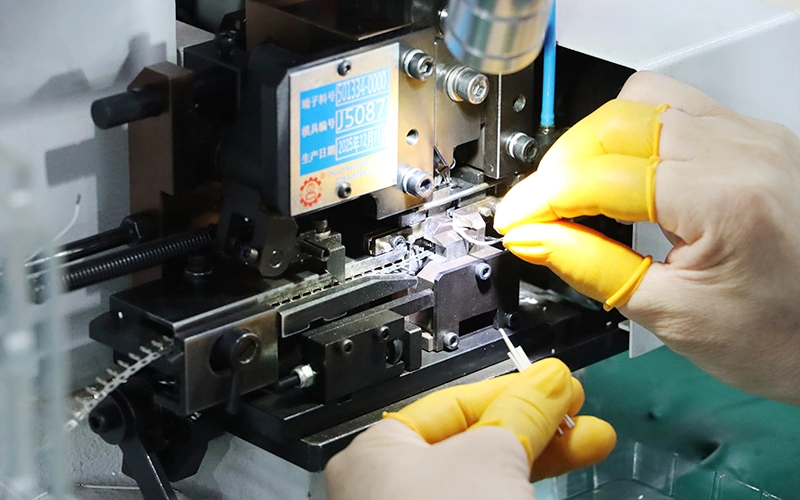
An applicator performs several coordinated tasks during every cycle. It advances the terminal strip, positions one terminal over the anvil, separates it from the carrier, locates the wire, forms the conductor crimp, and forms the insulation support. Each function depends on geometry developed for the intended terminal family.
The crimper profile must guide the terminal wings into the required shape. The anvil must support the barrel at the correct position and radius. The feed system must place the terminal consistently under the tooling, while the shear system must separate the carrier without distorting the functional area. The insulation tooling must provide strain relief without cutting the insulation or interfering with the conductor crimp.
Using tooling that appears physically similar is not sufficient. Small differences in barrel width, material thickness, wing length, carrier pitch, or terminal position can alter the final form. Terminal manufacturers therefore publish application-tooling specifications that identify permitted terminal series, wire sizes, reference dimensions, and qualification criteria. Molex tooling documentation, for example, states that a tool should be used only with the terminals and conductor sizes specified for it and warns that wire stranding and insulation variations can affect the result.
For custom assemblies, the approved tooling reference should be controlled in the manufacturing documentation. Operators should not substitute an applicator, die set, or terminal revision based only on visual similarity.
How Crimp Tooling Controls Crimp Height
Conductor crimp height is the measured height of the formed conductor barrel at a defined location. It is widely used as a non-destructive process-control characteristic because it provides a practical indication of how far the barrel and conductor bundle have been compressed. However, the target and tolerance must come from the applicable terminal specification, validated process, customer drawing, or agreed control plan.
The applicator directly influences this measurement through the crimper and anvil geometry, ram position, adjustment mechanism, and alignment. The press and setup also matter. Shut-height variation, loose mounting, contamination, incorrect stroke, terminal-position error, or deflection under load can shift the result even when the adjustment dial has not been intentionally changed.
A crimp height above the validated range can indicate insufficient compression. Depending on the design, this may leave excessive internal voids, reduce mechanical retention, or create an electrically less stable interface. A value below the range can indicate excessive compression, which may damage strands, thin or crack the barrel, or create a termination that passes an initial test but has reduced durability under vibration or flexing.
Crimp width and external appearance add useful information but do not replace the specified height measurement. Likewise, a stable average is not enough if the process spread is approaching a limit. Production teams should evaluate both the measured values and their trend over time.
Why Tool Wear Causes Gradual Crimp Drift
Applicators contain contact surfaces and moving components that experience repeated loading. Crimper and anvil edges can wear; terminal material can build up on tooling surfaces; feed fingers, shear components, guides, bearings, and adjustment mechanisms can loosen or deteriorate. Debris and insufficient lubrication can further affect terminal feeding and alignment.
Some wear creates visible defects, such as asymmetrical wings, a damaged bellmouth, excessive burrs, or terminal deformation. Other wear appears first as gradual movement in crimp height, pull-force results, force signatures, or process variation. The product may remain within specification for a period while the process moves steadily toward a limit.
This is why preventive maintenance should not rely only on a universal cycle-count rule. Tool life varies with terminal material, plating, size, production speed, press conditions, cleaning practices, lubrication, and the tooling design itself. Cycle counts are useful triggers, but measurement trends and inspection history should also influence maintenance intervals.
Why a Wire Change Requires Revalidation
Two wires carrying the same nominal AWG or metric size are not automatically identical in a crimping process. Their actual conductor area, strand count, individual strand diameter, conductor plating, compaction, and construction may differ. Insulation diameter and hardness can also vary by cable family or supplier.
These differences change how the conductor bundle fills the barrel and how the insulation support closes around the cable. A setting approved for one wire may produce a different crimp height, strand distribution, pull force, or insulation grip with another wire bearing the same nominal size.
Revalidation should therefore be considered when changing the wire manufacturer, part number, conductor construction, insulation material, terminal revision, applicator, press, or critical setup parameter. The required scope should be risk-based and defined by the drawing, terminal supplier, customer requirement, and quality plan. At minimum, the team should confirm material identity, strip quality, external crimp condition, conductor crimp height, and the applicable mechanical acceptance test before releasing the revised combination.
How to Validate Crimp Quality
No single inspection method explains every aspect of a termination. A robust validation plan combines complementary checks and defines which are used for setup approval, ongoing production, periodic verification, and engineering change control.
1. Material and Setup Verification
Before crimping begins, verify the terminal part number and revision, wire part number and size, applicator identification, press assignment, setup sheet, and approved parameters. Confirm that the terminal feeds squarely over the anvil and that the stripped conductor enters the barrel at the intended depth.
2. Visual and Dimensional Inspection
The first-off sample should be checked for characteristics such as conductor position, conductor brush, bellmouth, cutoff condition, terminal deformation, insulation position, exposed or damaged strands, and insulation damage. The applicable drawing or workmanship requirement determines what is acceptable.
Crimp height should be measured with a suitable instrument using a defined method and location. The instrument must be calibrated, and operators must avoid measuring over burrs, bellmouths, or other features that distort the reading.
3. Pull-Force Testing
A pull test is destructive and measures the mechanical retention of the conductor termination under specified test conditions. The sample preparation, pull rate, insulation-support treatment, and minimum value should follow the applicable terminal specification or agreed standard. IEC 60512-16-4 defines a test method for tensile strength of crimped connections.
Pull force is valuable, but it is not a complete description of internal geometry or long-term electrical behavior. A termination can produce an acceptable pull result while still showing a marginal conductor position, asymmetrical compression, damaged strands, or other concerns. Conversely, an incorrectly performed pull test can produce misleading data.
4. Cross-Section Analysis
Cross-section analysis cuts, prepares, and examines a crimp at a controlled location. It can reveal wing formation, strand distribution, compression symmetry, internal voids, cracks, strand damage, and the relationship between the conductor bundle and terminal barrel.
This method is especially useful during initial qualification, after major material or tooling changes, during troubleshooting, and at frequencies defined by the control plan. It is destructive and sample-based, so it should complement rather than replace routine dimensional checks. Acceptance must be based on product-specific criteria; arbitrary compression ratios should not be applied to every terminal design.
5. Crimp-Force Monitoring
Crimp-force monitoring compares the force signature generated during a cycle with a validated reference window. It can help detect changes such as missing strands, abnormal terminals, feeding errors, or process variation in real time. Komax describes crimp-force monitoring as a method for continuous cycle monitoring and production traceability.
However, force monitoring does not eliminate the need for correct setup, crimp-height verification, pull testing, or periodic destructive analysis. Its sensitivity depends on the application, sensor, reference samples, thresholds, and process stability. The system must be validated for the specific terminal and wire combination.
6. Electrical Verification
Continuity testing confirms that an electrical path exists, but it does not independently prove that a crimp has the required mechanical strength or low-resistance stability over its service life. Depending on the application, qualification may also include contact-resistance, voltage-drop, temperature-rise, vibration, thermal, or environmental testing.
IEC 60352-2:2024 provides general requirements, test methods, and practical guidance for solderless crimped connections used in electrical and electronic equipment. Project requirements may also reference IPC/WHMA-A-620F, terminal-manufacturer specifications, customer drawings, or industry-specific requirements. The governing criteria should be agreed before production.
Managing Applicators in Mass Production
Tooling management should convert engineering requirements into repeatable production controls. A practical system includes the following elements.
Unique Tool Identification
Each applicator should have a unique asset number linked to its terminal family, supported wire range, press compatibility, revision, maintenance record, and current status. Interchangeable tooling components should also be controlled where substitution could affect the crimp.
Controlled Setup Documentation
The setup sheet should identify the approved material combination, applicator and press, crimp-height target and tolerance, strip length, insulation-crimp setting, feed position, inspection method, sampling frequency, and reaction plan. Parameter changes should be made only by authorized personnel and recorded.
First-Article Confirmation
First-article inspection should be required at the start of a job and after conditions that may affect the result, such as an applicator change, maintenance, repair, material change, press change, extended stoppage, or parameter adjustment. Production should begin only after the required checks are accepted and documented.
In-Process Monitoring and Trend Review
Sampling frequency should reflect product risk, process capability, volume, customer requirements, and the effectiveness of automated monitoring. Crimp-height data should be reviewed as a trend, not merely as isolated pass/fail results. Force-monitoring alarms, pull data, visual defects, scrap, and maintenance findings can provide additional evidence of process movement.
Preventive Maintenance and Tool-Life Control
Maintenance typically includes cleaning, inspection, lubrication where specified, removal of terminal residue, verification of fasteners and alignment, inspection of wear surfaces, and replacement of approved wear components. The interval can begin with supplier guidance and cycle counts, then be refined using actual production history.
A tool should not be returned to production solely because maintenance has been completed. The defined first-article and validation checks must confirm that it still produces acceptable crimps.
Measurement-System Control
Crimp-height micrometers, tensile testers, microscopes, and monitoring systems must be suitable for the characteristic being measured. Calibration status, test fixtures, measurement methods, operator technique, and data recording all affect confidence in the result. Correlation checks are especially important when equipment, methods, or production locations change.
A Clear Reaction Plan
When a result exceeds a limit or shows abnormal drift, the response should be predetermined: stop the process, identify and segregate potentially affected material, trace production back to the last accepted check, inspect the wire and terminal, examine the applicator and press, correct the verified cause, and repeat approval testing before restart.
Adjustment alone is not root-cause analysis. Repeatedly changing crimp height without checking wear, material variation, feeding, alignment, and measurement method can hide a deteriorating process.
How FPIC Supports Controlled Terminal Crimping
FPIC manufactures custom wire harnesses and cable assemblies for industrial equipment, new energy systems, medical equipment, e-mobility, and other OEM applications. Based on project requirements, its wire harness manufacturing capability includes automatic wire cutting and stripping, terminal crimping, servo-controlled processing, connector assembly, inspection, electrical testing, and packaging.
FPIC’s documented quality assurance resources include a computer-controlled servo tensile tester for mechanical testing, dimensional measurement equipment, microscopes, cable harness testers, contact-impedance testing, and other electrical and environmental test instruments. Production and quality records can be supported through digital management systems, including PLM, ERP, MES, and WMS.
For a custom project, the required crimp controls should be established from the actual terminal, wire, application environment, customer drawing, and production volume. FPIC’s R&D and engineering support helps define appropriate tooling, first-article requirements, inspection frequency, validation tests, and traceability records without applying generic parameters to an unsuitable combination.
What OEM Buyers Should Ask a Harness Supplier
Before approving a supplier, ask how it controls the complete crimping process:
- Is each terminal and wire combination linked to approved tooling and parameters?
- What triggers first-article inspection and revalidation?
- How are crimp height, pull force, and visual characteristics controlled?
- When are cross-sections or additional electrical tests required?
- How are applicator cycles, maintenance, repairs, and wear parts recorded?
- Can production records trace the material, machine, tooling, inspection, and test status?
- What happens to output produced since the last accepted check if the process fails?
Clear answers show whether crimping is being managed as an engineered process or treated as a simple press operation.
Conclusion
Crimp tooling directly affects terminal positioning, barrel formation, conductor compression, insulation support, and production repeatability. Consistent wire harness crimping quality therefore requires more than selecting an automatic machine. It requires an approved terminal-wire-applicator combination, validated settings, first-article confirmation, complementary inspection methods, preventive maintenance, trend review, and a documented reaction plan.
If you are developing a custom wire harness, send FPIC your drawing, BOM, terminal and wire specifications, expected volume, application conditions, and required acceptance standards. Our OEM/ODM engineering team can review the manufacturability and verification requirements for your project.
Email: info@sz-fpi.com
Frequently Asked Questions
What is a terminal crimp applicator?
A terminal crimp applicator is precision tooling installed in a compatible press or automatic wire-processing machine. It feeds and positions terminals, supports them on an anvil, forms the conductor and insulation crimps, and separates each terminal from its carrier.
Can one applicator crimp different terminal types?
Only combinations approved by the tooling or terminal manufacturer should be used. Similar-looking terminals can have different material thicknesses, barrel geometry, carrier pitch, or forming requirements, so physical fit alone does not prove compatibility.
How often should crimp height be checked?
The frequency should be defined by product risk, process capability, production volume, customer requirements, and the available monitoring system. Checks are normally required during first-article approval and at controlled intervals during production, with additional verification after relevant changes or maintenance.
Why can a crimp pass a pull test but still be unacceptable?
Pull force evaluates mechanical retention under a defined test, not every aspect of the connection. Incorrect conductor position, asymmetric forming, strand damage, barrel defects, or unsuitable insulation support may require visual, dimensional, cross-sectional, or electrical evaluation.
When should an applicator be serviced or replaced?
Service decisions should consider supplier guidance, cycle count, inspection results, crimp-height trends, force-monitoring data, visible wear, feed accuracy, and defect history. There is no universal service-life value suitable for every terminal and production condition.
Does continuity testing prove crimp quality?
No. Continuity confirms that a conductive path exists at the time of testing, but it does not prove adequate mechanical retention, correct compression, stable contact resistance, or durability under vibration, temperature change, and long-term service.
Resources
- Komax Group – Entry into the Crimp Applicator Business
Komax’s August 2026 announcement describes its investment in KTK and the establishment of crimp-applicator manufacturing and assembly in Tianjin. - TE Connectivity – Terminal Crimping Applicators
An official overview of applicator components, crimp-height adjustment, terminal feeding, alignment, and maintenance-related design features. - Molex – Application Tooling Specification
A product-specific example showing the relationship between terminals, conductor sizes, crimp-height criteria, pull testing, and tooling limitations. - Komax – Crimp Force Monitoring
Explains how force signatures can support real-time detection, process monitoring, and traceability in automated wire processing. - Komax – Micrographs and Microscopy
Describes cross-sectional imaging and microscopy methods for verifying and documenting crimp connections. - IEC 60352-2:2024 – Solderless Crimped Connections
International guidance covering general requirements, test methods, and practical considerations for solderless crimped connections. - IEC 60512-16-4:2008 – Tensile Strength of Crimped Connections
Defines a standard test method for evaluating the tensile strength of crimped contacts and terminations. - IPC/WHMA-A-620F – Cable and Wire Harness Assemblies
The current industry-consensus standard for requirements and acceptance of cable and wire harness assemblies.