Strain Relief Design in Wire Harness Assemblies: Preventing Cable Failure
Strain Relief Design in Wire Harness Assemblies: Preventing Cable Failure
A wire harness can have the correct wire gauge, high-quality connectors, and excellent electrical performance, yet still fail prematurely if mechanical stress is not properly controlled.
One of the most important solutions is strain relief.
During installation and operation, a wire harness can experience:
- Pulling forces
- Bending
- Twisting
- Vibration
- Shock
- Repeated movement
- Thermal expansion and contraction
If these forces are transferred directly to the conductor, crimp, terminal, or connector, localized stress can eventually cause mechanical or electrical failure.
Proper strain relief helps distribute these forces over a larger area and prevents excessive loading at vulnerable transition points.
For automotive, industrial automation, robotics, energy storage, and other demanding applications, strain relief should therefore be treated as a fundamental part of wire harness mechanical design—not as an optional accessory.
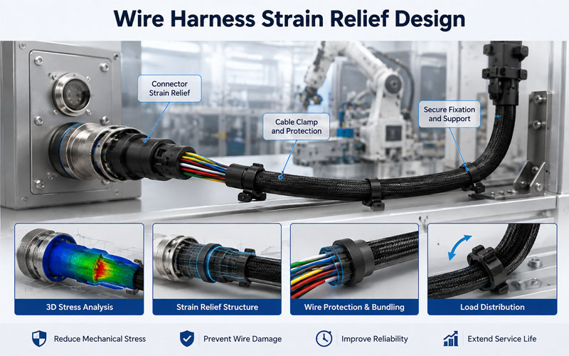
What Is Strain Relief in a Wire Harness?
Strain relief is a mechanical design feature that prevents external forces from being transferred directly to electrical termination points.
A simplified system is:
Cable → Strain Relief → Connector → Terminal
Without effective strain relief, pulling or bending the cable can place stress directly on the terminal or crimp.
With properly designed strain relief, the mechanical load is controlled before it reaches the electrical connection.
Common strain-relief solutions include:
- Overmolding
- Cable clamps
- Grommets
- Backshells
- Protective boots
- Retainers
- Cable ties
- Support brackets
- Flexible conduit
The appropriate solution depends on the cable construction, connector design, movement, environment, and application requirements.
Why Strain Relief Matters for Wire Harness Reliability
The termination area is often one of the most mechanically sensitive parts of a harness.
Consider a cable connected to a connector.
If the cable is pulled, the force may travel through:
Jacket → Conductors → Crimp → Terminal → Connector Housing
If the force is concentrated at the crimp or terminal, repeated loading can eventually cause:
- Crimp deformation
- Conductor breakage
- Terminal movement
- Contact instability
- Insulation damage
- Intermittent electrical failure
Strain relief interrupts this mechanical load path.
The goal is simple:
Keep mechanical forces away from the electrical termination.
1.Strain Relief Protects the Crimp Connection
A crimp connection is designed to create a reliable electrical and mechanical connection between the conductor and terminal.
However, it should not be used as the primary structural support for repeated external cable loads.
Excessive pulling or bending can place additional stress on the crimped conductor.
Potential results include:
- Broken strands
- Conductor pull-out
- Crimp deformation
- Increased contact resistance
A properly designed strain-relief system allows the cable jacket or support structure to absorb external mechanical forces instead.
2.Strain Relief Reduces Stress at the Connector Exit
The cable-to-connector transition is a common location for mechanical stress concentration.
A sharp change in direction can create a high-stress area.
For example:
Poor Design
Connector → Sharp Bend → Cable
versus:
Better Design
Connector → Strain Relief → Controlled Bend → Cable
The second configuration provides a smoother transition and reduces localized bending.
3.Bend Radius and Strain Relief Work Together
Strain relief and bend radius should not be treated as separate design topics.
A connector may have excellent strain relief but still experience cable failure if the cable is forced into an excessively tight bend.
The mechanical design should therefore consider:
Strain Relief + Bend Radius + Cable Flexibility
Together, these factors determine how mechanical loads are transferred through the harness.
For dynamic applications, this relationship becomes even more important.
4.Static Harnesses Still Need Strain Relief
Strain relief is not only required for moving harnesses.
Fixed harnesses can also experience:
- Installation loads
- Vibration
- Thermal expansion
- Equipment movement
- Maintenance handling
For example, a harness installed inside an industrial control cabinet may appear stationary but still experience vibration from motors or machinery.
A suitable strain-relief structure helps prevent these forces from being transferred directly to the connector.
5.Dynamic Harnesses Require More Careful Design
Robotic and automated systems can subject harnesses to thousands or millions of movement cycles.
Typical dynamic applications include:
- Robotic arms
- Drag chains
- Automated equipment
- Moving stages
- Servo systems
These applications can introduce:
- Repeated bending
- Torsion
- Acceleration
- Reversal forces
Strain relief must therefore accommodate movement rather than simply restrain the cable.
A rigid clamp in the wrong location can actually increase mechanical stress.
The design should allow controlled movement while preventing excessive loading at the termination.
6.Overmolding as a Strain Relief Solution
Overmolding is one of the most integrated approaches to strain relief.
During overmolding, a polymer material is molded around the cable and connector transition.
It can provide:
- Mechanical support
- Cable retention
- Environmental protection
- Controlled bend transition
- Improved handling durability
A well-designed overmold can create a gradual transition between the rigid connector and flexible cable.
This can reduce sharp stress concentration.
However, overmolding material and geometry must be selected according to:
- Cable diameter
- Flex requirements
- Temperature
- Chemical exposure
- Connector material
- Required flexibility
7.Cable Clamps and Retainers
Cable clamps provide another practical method of strain relief.
They can be positioned near the connector or along the harness route to support the cable.
Proper clamp design should consider:
- Clamp location
- Clamping force
- Cable diameter
- Jacket material
- Vibration
- Movement requirements
A clamp that is too tight may damage the cable.
A clamp that is too loose may fail to control movement.
The objective is controlled retention—not excessive compression.
8.Grommets Protect Harnesses at Panel Pass-Throughs
When a harness passes through a metal or plastic panel, the edge can create a potential abrasion and stress point.
A grommet can help:
- Protect the jacket
- Prevent abrasion
- Reduce sharp-edge contact
- Improve cable positioning
This is particularly important when harnesses pass through:
- Vehicle body panels
- Control cabinets
- Battery enclosures
- Machinery frames
- Sheet-metal structures
Panel interfaces should always be reviewed during mechanical routing design.
9.Strain Relief at Branch Points
Branch points are another area that can experience mechanical stress.
A harness may divide into several branches:
Main Trunk → Branch A + Branch B + Branch C
If the branches are poorly supported, movement can concentrate at the junction.
Potential problems include:
- Jacket damage
- Conductor fatigue
- Uneven loading
- Branch separation
Proper branch positioning, wrapping, sleeving, and retention can help distribute mechanical loads.
10.Connector Orientation Matters
Connector orientation can have a significant effect on strain relief performance.
If a connector is positioned directly against a wall or bracket, the cable may be forced into an unnatural bend.
Changing the connector orientation can create:
- More routing space
- Larger bend radius
- Better cable exit direction
- Easier service access
This is a simple but often overlooked DFM consideration.
11.Strain Relief for Shielded Harnesses
Shielded cables introduce additional considerations.
The strain-relief structure should not unintentionally damage:
- Shield braid
- Foil
- Drain wire
- Shield termination
Mechanical loading at the shield termination can affect both durability and EMC performance.
For industrial Ethernet, servo, sensor, and communication harnesses, engineers should evaluate:
Mechanical Strain Relief + Shield Termination + EMC Performance
as one system.
12.Strain Relief and Environmental Protection
A good strain-relief design can also support environmental protection.
Depending on the construction, strain relief can help protect against:
- Water
- Dust
- Oil
- Chemicals
- Abrasion
For sealed cable assemblies, the strain-relief interface must be compatible with the overall sealing architecture.
In some applications, strain relief and environmental sealing are integrated into the same overmold or connector backshell.
13.Material Selection Matters
The strain-relief material must balance flexibility and mechanical strength.
Potential material considerations include:
PVC
Often used for general-purpose cable protection where flexibility and cost are important.
TPU
Can provide good flexibility and abrasion resistance for demanding cable applications.
TPE
Can provide flexible mechanical transitions and is used in various cable and overmold designs.
The final material should be selected based on:
- Temperature
- Chemical exposure
- Flex cycles
- Abrasion
- UV exposure
- Required hardness
- Cable compatibility
14.Avoid Over-Constraining the Cable
A common mistake is assuming that more mechanical restraint always means better reliability.
It does not.
If a harness is restrained too aggressively, movement may become concentrated between two fixed points.
This can increase local bending stress.
A better approach is to define:
Where the Cable Should Move
and
Where the Cable Should Not Move
This is especially important for robotic and dynamic harnesses.
15.Strain Relief and Maintenance
Strain relief should also support serviceability.
Technicians may need to:
- Disconnect connectors
- Remove harnesses
- Replace modules
- Inspect terminals
- Re-route cables
A poorly designed strain-relief system can make maintenance difficult.
Good designs provide:
- Accessible fixing points
- Clear cable paths
- Appropriate slack
- Easy connector access
- Controlled cable retention
The goal is to protect the harness without making service work unnecessarily difficult.
16.Strain Relief Validation
A strain-relief design should be validated under realistic operating conditions.
Depending on the application, testing may include:
Pull Test
Evaluates resistance to axial loading.
Flex Test
Evaluates performance under repeated bending.
Vibration Test
Evaluates mechanical durability under vibration.
Thermal Cycling
Evaluates mechanical behavior across temperature changes.
Abrasion Test
Evaluates jacket and protective material durability.
Mating Cycle Test
Evaluates connector performance when repeated service operations are expected.
Testing requirements should be defined according to the application and applicable customer or industry standards.
Common Strain Relief Design Mistakes
| Design Mistake | Potential Consequence |
|---|---|
| No strain relief at connector exit | Cable and terminal stress |
| Tight bend after connector | Conductor fatigue |
| Excessive clamping force | Jacket damage |
| Clamp placed too far away | Poor load control |
| Rigid restraint on dynamic cable | Concentrated flex stress |
| Poor branch support | Harness fatigue |
| Ignoring panel edges | Abrasion and insulation damage |
| Incorrect overmold hardness | Reduced flex performance |
| Poor connector orientation | Forced cable routing |
| No mechanical validation | Unexpected field failures |
Wire Harness Strain Relief Design Checklist
Before releasing a harness design, engineers should review:
Mechanical Design
✔ Is the cable mechanically supported?
✔ Is strain relief provided near critical terminations?
✔ Is the bend radius controlled?
✔ Are branch points adequately supported?
Connector Interface
✔ Is the connector orientation suitable?
✔ Is the cable exit direction controlled?
✔ Are crimp and terminal areas protected from external loads?
Dynamic Applications
✔ Can the harness move freely where required?
✔ Are torsion and repeated bending considered?
✔ Is the expected flex life validated?
Environmental Protection
✔ Are panel pass-throughs protected?
✔ Is abrasion controlled?
✔ Are sealing and strain relief compatible?
Manufacturing
✔ Can the strain-relief feature be assembled consistently?
✔ Is the fixing location clearly defined?
✔ Can operators install the harness without excessive force?
How FPIC Supports Wire Harness Strain Relief Design
FPIC provides customized wire harness and cable assembly solutions with mechanical design considerations covering:
- Connector selection
- Cable routing
- Bend radius
- Strain relief
- Overmolding
- Protective sleeving
- Cable retention
- Crimping
- Electrical testing
- Mechanical validation
For complex harness assemblies, strain-relief requirements can be incorporated into the design and manufacturing process rather than added after assembly.
This helps OEM customers address mechanical reliability from the beginning of product development.
FPIC supports applications including:
- Automotive electronics
- Industrial automation
- Robotics
- Energy storage
- Control systems
- Industrial equipment
The objective is to create harness assemblies that maintain reliable electrical connections while resisting the mechanical stresses encountered during installation and operation.
Final Thoughts
Wire harness reliability depends on more than electrical continuity.
Mechanical forces can gradually damage a harness even when its electrical performance initially appears normal.
Proper strain relief helps protect the most vulnerable areas of the assembly by controlling:
Pulling + Bending + Vibration + Torsion + Movement
The best strain-relief design combines:
Correct Bend Radius + Suitable Materials + Controlled Routing + Proper Retention + Application-Specific Validation
For static harnesses, the focus is often on installation, vibration, and service handling.
For dynamic harnesses, the design must additionally account for repeated movement, torsion, and flex life.
Ultimately, strain relief is not simply a protective feature around a connector.
It is a critical part of the complete mechanical reliability strategy of the wire harness.
FAQ
What is strain relief in a wire harness?
Strain relief is a mechanical feature that prevents external forces from being transferred directly to the cable termination, crimp, terminal, or connector.
Why does a wire harness need strain relief?
Without proper strain relief, pulling, bending, vibration, and movement can create concentrated stress that may lead to conductor fatigue, crimp damage, terminal movement, or intermittent electrical failures.
What is the difference between strain relief and bend radius?
Bend radius controls how tightly a cable can curve, while strain relief controls how external mechanical forces are transferred to the cable and connector. Both should be considered together.
Is overmolding a good strain-relief solution?
Overmolding can provide an integrated mechanical transition between the connector and cable. Its suitability depends on the cable construction, material, temperature, flexibility, environment, and required service life.
Do fixed wire harnesses need strain relief?
Yes. Even fixed harnesses can experience vibration, thermal movement, installation loads, and maintenance handling. Appropriate strain relief can reduce stress on electrical terminations.
How should strain relief be tested?
Testing should reflect the actual application. Depending on the harness, this may include pull, flex, vibration, thermal cycling, abrasion, and connector mating-cycle tests.
Need a Wire Harness Designed for Mechanical Reliability?
FPIC provides customized wire harness and cable assembly solutions with engineering support for routing, bend radius, strain relief, overmolding, crimping, testing, and production.
Whether your application involves static installation, vibration, or continuous movement, we can help develop a harness solution designed around its actual mechanical and electrical requirements.
Contact FPIC to discuss your wire harness project.
Resources
- IPC/WHMA-A-620 – Cable and Wire Harness Assemblies
https://www.ipc.org/
Industry reference for requirements and acceptance criteria for cable and wire harness assemblies. - SAE International
https://www.sae.org/
Technical standards and engineering resources relevant to automotive electrical and mechanical systems. - IEC Standards
https://www.iec.ch/
International standards covering cables, connectors, electrical equipment, and related requirements. - IATF 16949
https://www.iatfglobaloversight.org/
Quality management requirements for organizations in the automotive supply chain.