
Wire Harness Bend Radius: How It Affects Cable Life and Reliability
A wire harness may pass electrical testing when it leaves the factory, but its long-term reliability can depend heavily on how tightly it is bent during installation and operation.
One of the most important mechanical considerations is bend radius.
If a harness is bent too tightly, the conductors, insulation, shielding, jacket, and internal components can experience excessive mechanical stress. In dynamic applications, repeated bending can accelerate fatigue and eventually cause electrical or mechanical failure.
This makes bend radius more than a packaging consideration.
It is a critical part of wire harness reliability engineering.
For automotive systems, robotics, industrial automation, energy storage equipment, agricultural machinery, and other demanding applications, engineers should evaluate bend radius from the earliest stages of harness design.
A reliable harness should not only fit the available space.
It should maintain its electrical and mechanical performance throughout its expected service life.
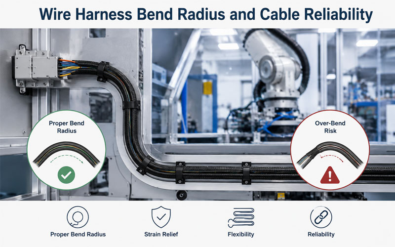
What Is Wire Harness Bend Radius?
Bend radius is the radius of the smallest curve that a cable or wire can safely follow without exceeding its specified mechanical limits.
It is commonly discussed as:
Minimum Bend Radius
For example, if a cable specification requires a minimum bend radius of 50 mm, routing the cable around a curve with a significantly smaller radius may create excessive mechanical stress.
The actual requirement depends on the construction of the cable or harness.
Factors can include:
- Conductor size
- Number of conductors
- Insulation material
- Jacket construction
- Shielding
- Cable diameter
- Flexibility
- Static or dynamic application
The cable manufacturer’s specified bend radius should always be treated as the starting point for engineering decisions.
Why Bend Radius Matters for Wire Harness Reliability
When a harness bends, different layers of the construction experience different mechanical stresses.
The outside of the bend is stretched.
The inside is compressed.
The neutral axis experiences less longitudinal strain.
When the bend is too tight, this deformation becomes more significant.
Over time, excessive bending can contribute to:
- Conductor fatigue
- Insulation cracking
- Jacket damage
- Shield deformation
- Terminal stress
- Connector loading
- Reduced flex life
The risk becomes greater when bending is repeated thousands or millions of times.
1.Bend Radius Affects Conductor Fatigue
The conductor is one of the most important components affected by repeated bending.
Copper conductors can withstand significant flexing when the cable is appropriately designed, but repeated deformation eventually creates fatigue.
The risk depends on:
- Conductor construction
- Strand size
- Strand count
- Cable flexibility
- Bend radius
- Number of cycles
- Movement speed
A highly flexible cable with fine-stranded conductors can generally tolerate repeated bending better than a cable designed primarily for fixed installation.
This is why the same conductor specification should not automatically be used for both static and dynamic applications.
2.Tight Bends Can Damage Insulation and Jackets
The conductor is not the only component under stress.
The insulation and outer jacket also deform during bending.
An excessively tight bend can cause:
- Cracking
- Permanent deformation
- Surface damage
- Loss of mechanical protection
Once the protective layers are damaged, moisture, chemicals, dust, or other environmental factors may reach internal components.
This can significantly reduce harness service life.
3.Static and Dynamic Bend Radius Are Different
One of the most important questions during harness design is:
Does the harness move during operation?
The answer determines how bend radius should be evaluated.
Static Bend Radius
A static harness remains essentially fixed after installation.
Typical applications include:
- Control cabinets
- Battery cabinets
- Fixed machinery
- Stationary electrical equipment
The harness may still experience vibration, thermal expansion, or occasional movement, but it does not continuously flex.
Dynamic Bend Radius
A dynamic harness repeatedly moves during operation.
Examples include:
- Robotic arms
- Drag chains
- Automated machinery
- Moving stages
- Flexible industrial equipment
Dynamic applications place much greater demands on:
- Cable construction
- Bend radius
- Strain relief
- Flexibility
- Routing geometry
A bend radius suitable for a fixed installation may not be sufficient for continuous motion.
4.Bend Radius and Cable Flex Life
Flex life describes how many bending cycles a cable or harness can withstand before its performance begins to deteriorate or failure occurs.
Bend radius is one of the major variables affecting flex life.
In general:
Smaller Bend Radius → Higher Mechanical Stress
Larger Bend Radius → Lower Mechanical Stress
However, bend radius should not be considered independently.
Flex life also depends on:
- Cable construction
- Conductor stranding
- Jacket material
- Shield design
- Movement speed
- Travel distance
- Temperature
- Installation method
For dynamic applications, engineers should evaluate the complete motion profile rather than relying on bend radius alone.
5.Shielded Cables Need Special Attention
Shielding adds another mechanical layer to the cable construction.
Depending on the design, repeated bending can affect:
- Braided shields
- Foil shields
- Drain wires
- Shield termination
- Overall cable diameter
Poor routing may eventually compromise shielding performance.
For applications with strict EMC requirements, engineers should evaluate both:
Mechanical Flexibility
and
Shielding Integrity
This is especially important for:
- Industrial Ethernet
- Servo systems
- Robotics
- Motor control
- Sensor systems
6.Connector Position Also Affects Bend Radius
The bend radius does not stop at the cable jacket.
The transition between cable and connector must also be considered.
A harness routed immediately into a sharp bend after the connector can create excessive stress at the termination point.
Potential consequences include:
- Terminal movement
- Seal deformation
- Crimp stress
- Connector damage
- Intermittent electrical connection
Proper strain relief helps distribute mechanical forces away from the termination.
A good design should therefore consider:
Cable → Strain Relief → Connector
as one mechanical system.
7.Bend Radius and Thermal Conditions
Temperature can change cable flexibility.
At low temperatures, some insulation and jacket materials become less flexible.
At high temperatures, materials may soften, age, or lose mechanical properties.
Therefore, bend radius should be evaluated under realistic operating conditions.
Relevant factors include:
- Minimum operating temperature
- Maximum operating temperature
- Thermal cycling
- Heat sources near the routing path
A routing design that performs well at room temperature may behave differently in a harsh operating environment.
8.Avoid Forced Bends During Installation
Even when the final routing appears acceptable, installation practices can create excessive stress.
Common problems include:
- Pulling the harness too tightly
- Forcing cables into narrow spaces
- Twisting the harness during installation
- Bending immediately behind connectors
- Using fasteners to create an excessively tight curve
The production process should therefore include clear routing and installation instructions.
Where necessary, fixtures or routing guides can help ensure repeatable installation.
9.Use Strain Relief to Protect Critical Areas
Strain relief prevents mechanical forces from being concentrated at sensitive termination points.
It can be provided through:
- Overmolding
- Connector backshells
- Cable clamps
- Grommets
- Protective boots
- Harness retainers
A properly designed strain-relief system helps transfer mechanical forces into the surrounding structure rather than directly into:
- Crimp terminals
- Solder joints
- Connector housings
- Conductor transitions
10.Bend Radius Should Be Considered During Harness Layout
Bend radius should be incorporated into the initial routing design rather than checked only after the harness is manufactured.
During layout review, engineers should consider:
Available Space
Is there enough room for the required bend?
Connector Orientation
Can the connector exit naturally without forcing the cable into a tight curve?
Branch Locations
Are branches positioned where they can bend without excessive stress?
Retention Points
Do clips and clamps support the harness without forcing sharp bends?
Service Access
Can technicians remove the harness without exceeding its allowable bend radius?
11.Common Wire Harness Bend Radius Mistakes
| Design Mistake | Potential Consequence |
|---|---|
| Bend radius too small | Excessive mechanical stress |
| Repeated tight bending | Conductor fatigue |
| Sharp bend near connector | Terminal and crimp stress |
| Poor strain relief | Premature termination failure |
| Ignoring dynamic motion | Reduced flex life |
| Incorrect cable construction | Early fatigue |
| Forced installation | Permanent cable deformation |
| Excessive clamping | Jacket or insulation damage |
12.How to Improve Bend Radius in Wire Harness Design
Several practical strategies can improve harness reliability.
Increase Available Routing Space
Where possible, create a larger routing path instead of forcing a tight curve.
Select Flexible Cable Construction
Dynamic applications may require:
- Fine-stranded conductors
- Flexible insulation
- Flexible jackets
- Appropriate shielding structures
Optimize Connector Orientation
Changing connector orientation can eliminate unnecessary bends near the termination.
Add Strain Relief
Use appropriate mechanical support to reduce stress concentration.
Optimize Fixing Points
Place clips and retainers so the harness follows a controlled path.
Validate Dynamic Movement
For moving applications, conduct flex testing that reflects actual operating conditions.
13.Bend Radius Requirements by Application
| Application | Bend Radius Priority | Key Considerations |
|---|---|---|
| Automotive | High | Vibration, temperature, packaging |
| Robotics | Very High | Continuous bending, torsion, flex life |
| Drag Chain | Very High | Repeated cycles, travel speed, cable construction |
| Energy Storage | Medium–High | Cabinet routing, thermal conditions, serviceability |
| Industrial Automation | High | Movement, vibration, EMI |
| Agricultural Equipment | High | Vibration, moisture, abrasion |
| Fixed Control Cabinet | Medium | Installation space and service access |
The exact bend radius should always be determined according to the selected cable construction and supplier specifications.
Wire Harness Bend Radius Design Checklist
Before releasing a harness design, engineers should review:
Mechanical
✔ Is the minimum bend radius known?
✔ Is the actual routing radius sufficient?
✔ Are dynamic and static conditions clearly distinguished?
✔ Are connectors protected from bending loads?
Cable Construction
✔ Is the conductor construction suitable for the application?
✔ Is the insulation flexible enough?
✔ Is the shielding structure appropriate?
Installation
✔ Can the harness be installed without forced bending?
✔ Are strain-relief features provided?
✔ Are fixing points positioned correctly?
Reliability
✔ Has the harness been tested under realistic movement?
✔ Are temperature and vibration conditions considered?
✔ Is the expected flex life sufficient?
How FPIC Supports Reliable Wire Harness Design
FPIC provides customized wire harness and cable assembly solutions for demanding applications.
Engineering evaluation can include:
- Cable construction
- Conductor selection
- Connector selection
- Bend radius
- Strain relief
- Protective sleeving
- Routing
- Electrical testing
- Mechanical reliability
For dynamic applications, harness design can be adapted to the required movement, installation environment, and expected service life.
By considering mechanical and electrical requirements together, FPIC helps OEM customers develop wire harness assemblies designed for reliable field performance.
Final Thoughts
Bend radius is one of the fundamental mechanical parameters in wire harness design.
A harness that is bent too tightly may experience mechanical stress long before an electrical problem becomes visible.
Over time, this can lead to:
- Conductor fatigue
- Insulation damage
- Shield degradation
- Connector stress
- Reduced flex life
The correct approach is to consider bend radius together with:
Cable Construction + Routing + Strain Relief + Movement + Environment
For static harnesses, the focus may be installation and long-term mechanical stability.
For dynamic harnesses, the design must additionally account for repeated motion and flex life.
Ultimately, good bend-radius design helps ensure that a wire harness does not simply pass factory testing—it continues to perform reliably throughout its intended service life.
FAQ
What is the minimum bend radius of a wire harness?
The minimum bend radius is the smallest recommended radius at which a cable or harness can be bent without exceeding its specified mechanical limits. The exact value depends on cable construction and application.
Why does bend radius affect cable life?
A smaller bend radius increases mechanical strain. Repeated bending can accelerate conductor fatigue, insulation damage, shielding degradation, and other failure mechanisms.
Is dynamic bend radius different from static bend radius?
Yes. Dynamic applications involve repeated movement and generally require a cable construction and bend-radius strategy specifically designed for continuous flexing.
Can a larger bend radius improve cable life?
Generally, reducing mechanical strain through a larger routing radius can improve durability, but actual service life also depends on conductor construction, materials, movement, temperature, and other conditions.
How can connector damage caused by cable bending be prevented?
Proper connector orientation, strain relief, routing clearance, and controlled bend radius near the termination can reduce mechanical loads on the connector and terminals.
Need a Wire Harness Designed for Long-Term Flex Life?
FPIC provides customized wire harness and cable assembly solutions for automotive, robotics, industrial automation, energy storage, and other demanding applications.
From cable selection and routing design to strain relief, assembly, and testing, FPIC supports OEM customers in developing reliable harness solutions.
Contact FPIC to discuss your wire harness requirements.
Resources
- IPC/WHMA-A-620 – Requirements and Acceptance for Cable and Wire Harness Assemblies
https://www.ipc.org/
Industry reference for cable and wire harness assembly requirements and acceptance criteria. - SAE International
https://www.sae.org/
Provides engineering standards and technical resources relevant to automotive electrical systems and harness applications. - IEC Standards
https://www.iec.ch/
International standards covering electrical equipment, cables, connectors, and related engineering requirements.