Prototype to Mass Production: Wire Harness Manufacturing Challenges
A wire harness that performs well in prototype testing is not automatically ready for mass production. Prototype builds typically involve limited quantities, close engineering supervision, and flexible assembly methods. Volume manufacturing introduces different demands: repeatable processes, stable material supply, controlled cycle times, documented inspection criteria, and consistent output across production batches.
The transition is particularly challenging when a harness contains multiple wire gauges, specialized terminals, complex branching, tight routing requirements, shielding, sealing, or application-specific electrical performance requirements. A minor design or process weakness that is manageable during a small prototype run can become a recurring quality issue when hundreds or thousands of assemblies are produced.
For OEMs and engineering teams, the objective is to establish production readiness before volume ramps up. This article examines the key challenges in scaling wire harness manufacturing and explains how structured engineering and manufacturing controls can reduce launch risks.
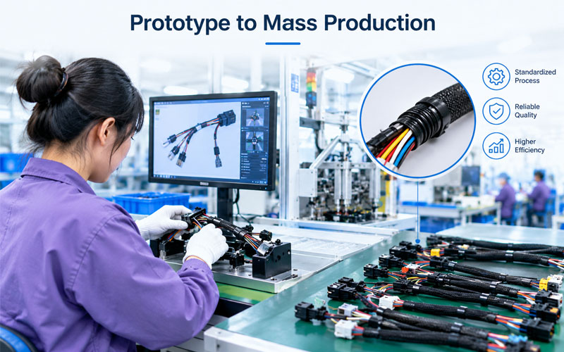
1.Why Prototype Success Does Not Guarantee Mass Production Readiness
Prototype production and mass production serve different purposes.
During prototyping, the main objective is to confirm that the design meets functional and application requirements. Engineers may use manual cutting, hand crimping, temporary fixtures, or flexible assembly sequences to build samples quickly and evaluate design feasibility.
Mass production requires a more disciplined approach. Every critical operation must be repeatable, measurable, and supported by appropriate tooling, work instructions, inspection methods, and material controls.
| Area | Prototype Stage | Mass Production Stage |
|---|---|---|
| Build method | Flexible, often manually assembled | Standardized and repeatable |
| Tooling | Temporary or adjustable fixtures | Validated production tooling |
| Process control | Close engineering supervision | Defined controls and documented records |
| Inspection | Detailed sample evaluation | Planned in-process and final verification |
| Material supply | Small quantities or samples | Stable supply with controlled specifications |
| Engineering changes | Relatively easy to accommodate | Require formal review and implementation |
| Production planning | Focused on sample completion | Focused on capacity, delivery, and consistency |
The key challenge is converting engineering knowledge into a manufacturing system that can deliver the same required result repeatedly, without depending on individual operator experience or frequent engineering intervention.
2.Design for Manufacturability: Identifying Problems Before the Production Ramp
Design for manufacturability (DFM) is one of the most important activities before a harness enters volume production.
A prototype may demonstrate electrical functionality while still containing features that are difficult to assemble efficiently. These issues can include insufficient wire lengths for routing, crowded connector exits, inaccessible terminal cavities, complicated branch points, excessive variations in wire preparation, or protective coverings that are difficult to install consistently.
2.1 Review the complete assembly process
DFM reviews should consider the entire manufacturing sequence rather than individual components in isolation.
Engineers should evaluate:
- Wire cutting and stripping requirements, including insulation type and conductor size.
- Terminal compatibility with the specified conductor and insulation dimensions.
- Connector cavity access and terminal insertion direction.
- Branch locations, wire lengths, and routing tolerances.
- Sleeve, braid, tape, conduit, and other protective covering installation.
- Label placement, identification requirements, and inspection accessibility.
- Fixture access and the possibility of incorrect assembly.
For example, a complex branch arrangement may fit the intended installation space but create unnecessary handling during assembly. Adjusting branch lengths, defining a clearer assembly sequence, or redesigning the fixture may improve repeatability without changing the harness’s intended function.
2.2 Separate functional requirements from manufacturing preferences
Not every difficult assembly feature should be changed. Some requirements are essential to fit, electrical performance, environmental protection, or serviceability.
A structured review should distinguish mandatory design requirements from features that may be optimized. Any proposed design modification must be reviewed and approved through the appropriate engineering process before implementation.
Practical recommendation: Conduct a cross-functional DFM review involving design engineering, manufacturing engineering, quality, procurement, and the customer where required. Resolving manufacturing risks before tooling and material commitments increase is generally less disruptive than correcting them during a production launch.
3.Process Validation: Turning a Successful Sample into a Repeatable Process
A prototype confirms that an assembly can be built. Process validation provides evidence that the selected manufacturing method can repeatedly produce assemblies meeting defined requirements.
This distinction is critical because a prototype may pass inspection even when the process is sensitive to operator technique, tooling adjustment, material variation, or assembly sequence.
3.1 Validate critical production operations
The validation plan should reflect the actual design and risk profile of the harness. Depending on the product, key operations may include:
- Wire preparation: Verify cut lengths, strip lengths, conductor condition, and insulation integrity.
- Terminal crimping: Confirm the approved tooling setup, crimp dimensions where specified, and applicable pull-force or other mechanical verification.
- Terminal insertion: Verify cavity assignment, terminal seating, locking features, and secondary locking devices where applicable.
- Splicing and joining: Confirm the approved joining method and its applicable acceptance criteria.
- Shielding and protection: Check shield termination, grounding arrangements, sleeve coverage, sealing, and strain relief as required by the design.
- Electrical testing: Verify continuity, incorrect connections, shorts, and insulation performance where specified.
Not every harness requires every test or validation method. Test selection and acceptance limits should be based on product specifications, customer requirements, applicable standards, and documented risk assessment.
3.2 Establish objective acceptance criteria
Terms such as “good crimp,” “secure terminal,” or “proper routing” are insufficient as standalone production instructions.
Operators and inspectors need defined criteria, such as approved tooling settings, dimensional limits, visual acceptance examples, test limits, and defect escalation rules.
IPC/WHMA-A-620 is a widely recognized industry standard for cable and wire harness assembly workmanship and acceptance. It addresses areas such as crimped, mechanically secured, and soldered interconnections. Manufacturers should determine the applicable revision, product class, customer-specific requirements, and contractual acceptance criteria before using it as a production reference.
A validated process should also specify what happens when results fall outside approved limits. Without a clear reaction plan, an abnormal result may lead to inconsistent adjustments or the continuation of production under uncontrolled conditions.
4.Tooling and Fixture Readiness: Avoiding Hidden Sources of Variation
Production tooling can improve consistency, but only when it matches the product design, manufacturing method, and expected production volume.
A prototype may be assembled using a universal board or temporary fixture. During volume production, this approach may create excessive setup time, inconsistent branch positioning, routing errors, or difficulty maintaining dimensional repeatability.
4.1 Match fixture design to the harness configuration
Fixtures should support the assembly’s critical geometry without making installation or removal unnecessarily difficult.
Key considerations include:
- Repeatable location of connectors and branch points.
- Clear routing paths for individual wires and bundles.
- Access for terminal insertion and locking verification.
- Protection against wire stretching, pinching, or incorrect placement.
- Inspection access for critical dimensions and assembly features.
- Practical changeover when producing different harness variants.
For complex harnesses, fixture design should also consider how operators will identify and recover from incorrect routing or missing components.
4.2 Evaluate production tooling under realistic conditions
A fixture that works well for a few samples may not remain practical during a full shift or repeated production runs.
Production trials should assess setup time, operator ergonomics, cycle-time variation, handling difficulties, and the ability to maintain the required assembly dimensions. Tooling adjustments should be documented, and any change that could affect product conformity should follow the applicable change-control process.
The goal is not necessarily to automate every operation. It is to select tooling and workholding methods that support reliable output at the required volume and product mix.
5.Material Readiness and Supplier Consistency
A prototype build may use small quantities of available materials, while mass production depends on a stable and controlled supply chain.
Wire, terminals, connector housings, seals, protective sleeving, labels, and other components must conform to the approved specifications. Substituting a visually similar component can introduce compatibility, assembly, or performance problems.
5.1 Confirm specifications and approved alternatives
Before the production ramp, manufacturers should confirm:
- Exact part numbers and revisions for wires, terminals, connectors, and accessories.
- Conductor size, insulation material, temperature rating, and other required wire properties.
- Terminal and connector compatibility, including applicable plating or material requirements.
- Seal, sleeve, and protective-covering specifications.
- Label content, identification format, and traceability requirements.
- Approved alternate materials and the conditions under which they may be used.
Where a component becomes unavailable, an alternative should not be introduced solely because it appears dimensionally similar. Engineering review, compatibility checks, and customer approval may be necessary.
5.2 Align purchasing with production planning
Long-lead components and custom tooling can become launch bottlenecks. Procurement planning should be linked to the approved bill of materials, forecast demand, supplier lead times, minimum order quantities, and planned production ramp.
Material readiness also requires revision control. If a prototype used an earlier component revision, the production team must confirm that the approved production version is available and that the corresponding drawings, work instructions, and inspection documents are aligned.
6.Engineering Change Control: Managing Revisions Without Losing Traceability
Engineering changes are common during product development. Prototype testing may reveal routing conflicts, assembly difficulties, incorrect lengths, or opportunities to improve reliability.
The challenge is ensuring that approved changes are implemented consistently across materials, tooling, documentation, and production.
An uncontrolled revision can result in multiple harness configurations being assembled under the same part number or in the use of outdated work instructions after a design update.
6.1 Define a controlled change process
A robust change process should identify:
- The reason for the proposed change and the affected product requirements.
- The impact on drawings, bill of materials, tooling, process settings, and inspection plans.
- Any required testing, risk assessment, or customer approval.
- The effective date, production order, or lot from which the change applies.
- The disposition of existing inventory, work in progress, and previously built assemblies.
- The records needed to demonstrate that the correct revision was used.
6.2 Maintain configuration consistency
Production documents should identify the applicable revision and provide a clear link between the assembly, its approved materials, and the relevant manufacturing instructions.
Where traceability is required, production records should make it possible to investigate which revision, material lot, tooling setup, and inspection results applied to a particular batch or assembly.
This is especially important when prototype samples and production units are built during overlapping development phases.
7.Quality Control at Higher Production Volumes
As output increases, a small process weakness can affect a much larger number of assemblies. Quality planning should therefore move beyond checking whether individual prototype samples meet specifications.
The objective is to detect variation early, prevent recurring defects, and verify that the manufacturing process remains stable.
7.1 Build a risk-based inspection plan
Inspection methods and frequencies should reflect the failure risk, process capability, customer requirements, and applicable product standards.
| Process or feature | Example control method | Purpose |
|---|---|---|
| Wire cutting and stripping | Length measurement and visual checks | Detect incorrect dimensions or conductor damage |
| Crimp termination | Tooling verification, visual inspection, and applicable mechanical tests | Confirm termination quality |
| Terminal insertion | Seating, locking, and cavity-position checks | Prevent incomplete or incorrect assembly |
| Harness routing | Fixture-based or dimensional checks | Maintain branch and routing geometry |
| Electrical connections | Continuity and short-circuit testing | Detect wiring and connection errors |
| Insulation or isolation | Specified insulation resistance or dielectric testing, where applicable | Verify required electrical insulation performance |
| Identification | Label and revision verification | Maintain correct product identification |
A continuity test does not establish that every mechanical or environmental requirement has been satisfied. Similarly, a visual inspection alone cannot verify all electrical characteristics. Each method should be assigned to the failure modes it can reasonably detect.
7.2 Monitor trends instead of relying only on pass/fail results
During the ramp-up phase, useful indicators may include first-pass yield, rework rate, defect categories, crimp-related nonconformities, electrical test failures, cycle-time variation, and delivery performance.
Reviewing trends can reveal recurring issues before they become widespread. For example, a gradual increase in terminal insertion failures may indicate a tooling, component, or operator-method issue even when most assemblies still pass final inspection.
Control limits, sampling methods, and reaction plans should be defined according to the relevant process and quality requirements. Production teams should investigate abnormal trends rather than relying exclusively on final inspection to screen out defects.
8.Capacity Planning and the Production Ramp-Up
A process that can produce a small prototype quantity may not meet the required production schedule. The transition to mass production therefore requires a realistic assessment of capacity, labor, equipment availability, material supply, and production mix.
8.1 Calculate capacity using actual process conditions
Capacity estimates should account for more than nominal machine speed. Relevant factors include:
- Actual cycle times and setup or changeover time.
- Available production hours and planned maintenance.
- Operator availability and skill requirements.
- Material replenishment and internal logistics.
- Inspection and testing capacity.
- Expected rework and process interruptions.
- Demand fluctuations and product-mix changes.
Bottlenecks may occur at manual assembly, terminal insertion, electrical testing, or material preparation even when upstream equipment has spare capacity.
8.2 Use staged production builds
A controlled ramp-up allows the team to identify problems before full production commitments are made.
A practical sequence may include:
Engineering prototype → Process trial → Pilot build → Production validation → Controlled ramp-up → Stable mass production
Each stage should have defined entry and exit criteria. These may include approved documentation, completed validation activities, acceptable defect trends, sufficient material availability, trained operators, and confirmed production capacity.
For automotive or other customer-regulated programs, formal production approval requirements may apply. AIAG’s Production Part Approval Process (PPAP), for example, is intended to help establish that production processes can consistently meet engineering design and specification requirements under actual production conditions.
The applicable approval method depends on the customer’s requirements and the industry involved.
9.Documentation and Workforce Readiness
Manufacturing consistency depends on more than equipment and inspection systems. Operators, technicians, inspectors, and production planners need access to the same approved information.
During prototype development, engineers may communicate process details directly to a small team. This informal knowledge becomes a risk when multiple shifts, workstations, or manufacturing sites are involved.
Before mass production, manufacturers should establish controlled versions of:
- Manufacturing process flow and work instructions.
- Approved bills of materials and engineering drawings.
- Tooling setup and maintenance instructions.
- Inspection criteria and test procedures.
- Operator training and qualification records, where required.
- Nonconformance handling and escalation procedures.
- Product identification and traceability records.
Training should focus on operations that directly affect product conformity, including correct terminal handling, wire preparation, connector assembly, routing, locking verification, and defect recognition.
When process instructions change, affected personnel should receive the updated information before the change is implemented.
10.A Practical Checklist for Wire Harness Production Readiness
Before committing to full-volume manufacturing, engineering and operations teams should review the following areas.
- Design requirements, drawings, and bill of materials are approved and aligned.
- DFM risks have been reviewed and critical assembly issues addressed.
- Materials and approved alternatives are confirmed.
- Production tooling and fixtures have been evaluated under realistic conditions.
- Critical manufacturing operations have documented process settings and acceptance criteria.
- Required electrical, mechanical, and other validation activities are complete.
- Inspection methods, test coverage, and reaction plans are defined.
- Engineering change control and revision traceability are established.
- Operators and inspectors are trained on approved instructions.
- Production capacity, material replenishment, and delivery plans are realistic.
- Pilot or production-validation results meet the agreed acceptance criteria.
- Applicable customer approval and submission requirements are satisfied.
Not every project requires the same documentation or validation depth. The readiness plan should be scaled to the harness complexity, application risk, production volume, and customer requirements.
How FPIC Supports Wire Harness Development and Production
Moving from prototype to mass production is a cross-functional engineering task. Design feasibility, material selection, manufacturing methods, inspection requirements, and delivery planning must work together rather than being handled as isolated activities.
FPIC brings 23 years of experience in connector and cable assembly manufacturing. For wire harness projects, early technical communication helps align application requirements with assembly feasibility, process planning, and production expectations.
When evaluating a new harness project, customers can share the available drawings, bill of materials, target quantities, operating conditions, and validation requirements. This information helps establish the scope of engineering review and identify potential manufacturing issues before the production ramp.
The appropriate approach depends on the product. A low-volume industrial harness may require a different tooling and validation strategy from a high-volume automotive assembly or a power harness for energy storage equipment. Establishing these differences early helps teams make more informed decisions about cost, quality, and lead time.
Conclusion
The transition from prototype to mass production is a critical stage in wire harness manufacturing because it tests whether the design can be produced consistently under real manufacturing conditions.
The most common challenges involve design manufacturability, process validation, tooling readiness, material consistency, engineering change control, quality planning, and production capacity. Addressing these areas before the ramp-up reduces the risk of repeated rework, delayed launches, and inconsistent output.
A successful production launch does not depend on a single machine or inspection step. It depends on a coordinated system that connects engineering requirements with repeatable processes, trained personnel, controlled materials, and objective quality evidence.
FAQ
Why is it difficult to move a wire harness from prototype to mass production?
Prototype builds often rely on flexible assembly methods and close engineering supervision. Mass production requires standardized processes, repeatable tooling, stable material supply, documented acceptance criteria, and sufficient capacity to meet demand consistently.
What should be checked before scaling up wire harness production?
Key checks include design and BOM approval, DFM review, material readiness, tooling validation, process capability, electrical testing, inspection planning, operator training, traceability, and production capacity.
How can manufacturers reduce defects during a production ramp-up?
They can use staged production builds, validate critical processes, establish clear acceptance criteria, monitor defect trends, and define reaction plans for abnormal results. Early feedback from production trials should be incorporated into controlled process improvements.
Why is design for manufacturability important for wire harnesses?
DFM identifies design features that may cause assembly difficulties, inconsistent routing, excessive handling, or inspection challenges. Resolving these issues before volume production can reduce rework and improve manufacturing repeatability.
Which standards are relevant to wire harness production readiness?
IPC/WHMA-A-620 provides workmanship and acceptance requirements for cable and wire harness assemblies. Automotive projects may also require customer-specific quality planning and production approval processes, such as APQP and PPAP. The applicable requirements depend on the product, industry, and customer agreement.
When should a wire harness manufacturer begin production planning?
Production planning should begin during prototype development, not after design approval. Early review of tooling, material lead times, validation needs, labor, capacity, and quality controls allows potential launch risks to be addressed before they affect delivery.
Planning to move a wire harness from prototype to mass production?
FPIC can discuss your harness design, target production volume, application requirements, and manufacturing considerations to help identify the next steps for your project.
Share your drawings or technical specifications with our team to start a project review.
Resources
- IPC/WHMA-A-620: Requirements and Acceptance for Cable and Wire Harness Assemblies
An industry-consensus reference covering workmanship and acceptance criteria for cable and wire harness assemblies, including crimped, mechanically secured, and soldered interconnections. - AIAG Quality Core Tools
An overview of automotive quality planning and related tools, including APQP, Control Plans, and PPAP, which can support structured production readiness. - AIAG: Implementing APQP, Control Plan and PPAP
Explains how process flow diagrams, work instructions, control plans, and production approval activities fit into a structured quality planning process.