Why Wire Harness Assembly Fixtures Matter for Manufacturing Consistency
Wire harness assembly fixtures translate an approved harness layout into repeatable physical references for connector position, wire routing, branch direction and component placement. Two harnesses can follow the same drawing yet differ because flexible wires move during handling, routing and bundling. A suitable fixture reduces that freedom while preserving the intended dimensions and avoiding assembly stress.
For industrial equipment manufacturers, the value is practical: assemblies should reach their interfaces, follow the intended route and fit the equipment consistently. FPIC supports custom harness projects with tooling preparation, assembly, inspection and testing according to the agreed scope. Fixture design and verification should therefore be considered alongside the harness drawing, rather than added only after inconsistent builds appear.
Why the Same Drawing Can Produce Different Assemblies
A drawing defines the required product, but it does not physically hold a connector or locate a breakout. During manual assembly, an operator may rotate a housing, distribute slack differently, move a branch while taping or tighten ties in a different sequence. Individual wire lengths can remain correct while the finished arrangement changes.
Consider an illustrative control harness with one main connector and several sensor branches. One assembler positions the main connector first and routes each branch outward. Another starts at the farthest sensor connector and draws the trunk toward it. Without shared locating references, the two methods can distribute available length differently around bends and branch transitions.
The result may be a connector facing the wrong direction, a breakout crowded against a clamp or a sleeve ending in an inconvenient position. These differences can complicate installation even when electrical connections are correct.
This is a process-control issue as well as a drawing issue. Clear requirements remain essential, but repeatable assembly also needs a practical way to maintain those requirements while work is performed.
What Is an Assembly Fixture?
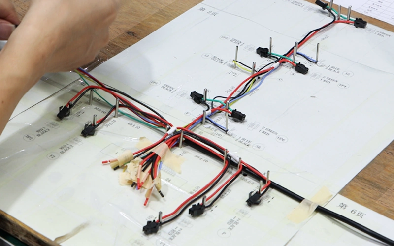
An assembly fixture supports and locates a harness during manufacture. Depending on the product, it may use a formboard, connector nests, routing posts, branch guides, component holders, adjustable stops or removable supports. A wire harness assembly jig is often used as an alternative shop-floor term, although terminology varies between manufacturers.
Panduit’s published harness-board information describes reusable grid tiles and mounting pegs for routing and forming wires. This illustrates one modular approach; it does not mean every harness needs the same board system or that FPIC uses that particular equipment. [1]
The appropriate design depends on geometry, assembly sequence, product mix and production quantity. A short point-to-point lead may need only a simple locator. A branched industrial harness may benefit from several coordinated references. More supports are useful only when they improve control without creating handling difficulties or unintended constraints.
Dedicated tooling can simplify setup for a stable, repeated design. Modular tooling can suit changing product families, provided its settings and changeover checks are controlled. Evaluate the complete operating effort: setup, loading, assembly access, inspection, maintenance and removal. A fixture that saves routing time but makes every completed harness difficult to release may offer little practical improvement.
Assembly, Electrical-Test and Dimensional Fixtures Have Different Jobs
Similar-looking tooling can serve different purposes. Define the function before deciding what a fixture proves.
| Fixture type | Primary purpose | Important limitation |
|---|---|---|
| Assembly fixture | Locate connectors, guide routing and support repeatable component placement during construction | Does not automatically verify circuit mapping, finished dimensions or hidden workmanship |
| Electrical test fixture | Connect the harness to a tester through adapters, mating connectors or suitable contacts | Evaluates only the electrical characteristics covered by the approved program and method |
| Dimensional inspection fixture | Support a defined measurement condition or compare specified features against approved references | Does not establish electrical correctness or validate every installed routing condition |
One station may combine these functions, but each requires its own approved method. A connector nest can position a housing without contacting its circuits. An electrical adapter can connect every pin while allowing the branch to sit in the wrong position.
Cirris explains that the interface between the harness and tester also needs verification. Incorrect fixture wiring or unreliable contacts can affect the test result. [2] Similarly, a board used for assembly should not be treated as a qualified dimensional gauge merely because its outline resembles the drawing.
Start Fixture Design with the Harness Requirements
Establish the references that matter
Begin with the current harness drawing, BOM, wiring definition, connector information and installation requirements. Identify the features that actually determine fit: connector interfaces, branch locations, clips, grommets, protective transitions and cable exits.
The fixture references should correspond to the drawing’s dimensional datums. A stop that locates the rear of a housing may not establish a dimension defined from its mating face. Connector-to-connector distance also differs from a wire cut length or a distance measured along a curved bundle.
Resolve unclear datums before manufacturing tooling. Fixture design should not silently create a product requirement missing from the approved documentation.
Define the assembly condition
Flexible harnesses change shape with handling. Agree whether critical dimensions are evaluated on the board, in a supported relaxed condition or in a representative installation. Define any permitted straightening or specified measuring load rather than allowing operators to pull until the assembly reaches its stops.
The assembly condition and final acceptance condition may differ. Their relationship needs to be understood, particularly when tape, conduit, sleeves or backshells change the finished geometry. The fixture should support the approved manufacturing method without disguising insufficient length or forcing a nonconforming harness into position.
Avoid overconstraining the flexible assembly. Holding every connector rigidly while pulling each branch tight can make the product appear correct only while it remains clamped. Supports should distinguish the features that establish position from those that simply carry bundle weight. During trials, release and reload the harness using the approved method, then check whether critical relationships remain acceptable without compensating by hand. Persistent springback, difficult seating or inconsistent slack distribution should trigger investigation of the drawing interpretation, material behavior and process sequence.
Control Connector Position and Orientation
Connector location involves more than an endpoint on a board. The mating direction, latch position, keyway, cable exit and rotational orientation can all matter to installation.
A suitable nest should locate a robust, defined housing feature and provide access for the necessary assembly operations. It should avoid loading contact surfaces, seals, terminal locks or delicate latches. Retention needs to hold the component consistently without damaging it or distorting its relationship to the cable.
For a right-angle connector, controlling only the housing center may leave the cable exit facing the wrong way. For similar branches, clearly identified nests can help distinguish connector destinations. Where practical, physical keying can discourage incorrect placement, but its effectiveness must be checked using the actual permitted components.
A housing seated in its nest does not prove that terminals are fully inserted, locks are engaged or cavities are correctly populated. Those characteristics still require the specified assembly checks and electrical verification.
Guide Wire Routing and Branch Formation
Routing guides help operators follow the intended path while distributing wires into the correct branches. Their spacing and shape should support the actual bundle, including insulation diameter, protective materials, crossings and assembly access.
Branch formation deserves particular attention. A guide may identify where wires separate, but tape application, tie placement and handling can move the finished transition. The process should define when the branch is located, when it is secured and which feature becomes the inspection reference.
Useful fixture controls include:
- Identified branch channels that separate similar legs during assembly.
- Supports near breakouts to limit movement while protection is applied.
- Location references for clips, grommets and sleeve endpoints where required.
- Space for the specified bends, bundle thickness and intended slack.
- Removable features that allow the finished harness to leave the fixture without distortion.
Avoid routing wires tightly around small posts simply to match a flat outline. Bend requirements come from the applicable cable and assembly specifications, not from the diameter of the available hardware. Posts should guide placement without pinching insulation, stretching conductors or unintentionally changing twisted-pair or shielded-cable construction.
For complex three-dimensional routes, a flat formboard may represent manufacturing geometry rather than the installed shape. A representative equipment trial or installation fixture may still be needed to confirm access, clearances and interface alignment.
Design for the Actual Assembly Sequence
A fixture that holds the final shape can still obstruct the work needed to create it. Review how components enter the tooling, when connectors are terminated, how sleeves are installed and how the finished assembly is removed.
For example, a closed holder may support a branch during routing but trap it after a larger connector or molded feature is added. A connector clamp may prevent access to a secondary lock. A tall routing post may make taping awkward and encourage operators to lift the harness away from its references.
Trial the full sequence rather than checking only whether a completed sample fits. Include material loading, terminal insertion where applicable, protection application, identification, inspection access and removal.
Keep necessary checks visible before coverings conceal them. The tooling should allow operators and inspectors to examine branch routing, locking features and component placement at the appropriate stage. Clear instructions and suitable workholding reinforce each other: the instruction defines the operation, while the fixture helps maintain the intended physical condition.
Verify Repeatability Before Releasing the Fixture
A successful sample shows that one assembly can be made. Fixture release should also establish that the approved setup supports consistent results under representative production conditions.
A practical verification plan should consider:
| Verification activity | Question to answer |
|---|---|
| Compare tooling with approved data | Do locating references match the correct part and drawing revision? |
| Check loading and removal | Can the harness be assembled and released without forced handling or damage? |
| Evaluate repeated builds | Do critical features remain acceptable across the planned operating conditions? |
| Verify finished geometry | Does the product conform after release from the assembly supports? |
| Review installation fit | Are critical equipment interfaces and routing constraints represented adequately? |
| Review error opportunities | Can similar connectors, branches or variants be placed incorrectly? |
Where relevant, include different trained operators or shifts in the trial. The quantity, acceptance criteria and records should follow project risk and customer requirements; there is no universal sample count for every harness manufacturing fixture.
Use independently established measurements or checked reference data for critical features. If the same misplaced stop both creates and accepts a branch location, repeated builds can look consistent while all sharing the same error. Check the fixture itself and the finished product against the approved requirement.
Maintain Tooling and Control Product Changeovers
Fixture performance can change after release. Loose routing posts, worn nests, damaged retainers, debris, faded identifiers or unapproved adjustments can shift the assembly condition. Maintenance should address the features that influence product conformity, not only whether the board remains usable.
Identify the fixture and its applicable configuration. Link relevant revisions to the drawing, work instruction and inspection method. For adjustable or modular tooling, record the approved setup sufficiently clearly to reproduce it after changeover.
Before restarting a different variant, confirm:
- The correct product, drawing and fixture configuration are selected.
- Previous components and identification materials have been cleared.
- Locators, nests and branch guides match the approved setup.
- Required first-piece checks and release records are complete.
- Any separate electrical adapters and programs match the same product configuration.
A connector substitution, branch change or protection-material change may affect tooling even when the overall harness length remains unchanged. Assess the impact before implementation. A fixture repair may also require dimensional rechecking or renewed production approval when it could alter a critical reference.
Where tooling is used for measurement or acceptance, define the applicable verification, calibration or measurement-system controls according to its function. Not every assembly support requires the same controls as a dimensional gauge.
Connect Fixture Control with Inspection and Electrical Testing
Wire harness production consistency needs complementary evidence. Assembly tooling helps control placement; inspection evaluates defined physical features; electrical testing checks the specified circuits and electrical characteristics.
A continuity pass cannot establish branch position, connector clocking, protection coverage or installation clearance. Likewise, a visually tidy harness on a board can still contain a wrong connection, incomplete locking or a termination defect.
Select checks around the product’s failure risks and the stage where each feature remains accessible. Reinspect and retest after rework when the affected characteristics require it. Records should identify enough of the product and process configuration to investigate a recurring problem without assuming that every project needs identical data collection.
The main question is whether the combined controls prevent or detect the relevant failure. Adding more tooling does not help if the method, requirement or acceptance decision remains unclear.
How FPIC Supports Fixture Planning for Custom Harnesses
FPIC’s manufacturing capability and factory tour page identifies tooling preparation and wire harness assembly resources. Its prototyping and NPI services include project planning for required tooling or fixtures and production-transfer activities within the approved scope. [3][4]
For industrial equipment wire harnesses, fixture planning should connect connector interfaces, branch geometry, assembly access and the required installation condition. Manufacturing and inspection resources should be selected around those project needs.
FPIC’s quality assurance resources cover in-process control and project-related dimensional, visual and electrical verification. The specific fixture design, inspection method, verification frequency and retained records must be confirmed for the actual assembly. These published capabilities do not imply that every harness uses a dedicated board, automatic error detection or a universal dimensional tolerance. [5]
Send the Information Needed for a Repeatable Build
For a custom OEM/ODM harness project, provide the current drawing and revision, BOM, wiring map, connector specifications and expected quantity. Include critical datums, branch directions, connector clocking, protective-component locations and any equipment-side routing information. [6]
Explain which features are difficult to install, which operations need access and how finished dimensions will be accepted. If tooling already exists, provide its drawings, setup information and known limitations where available.
Send FPIC your harness drawing and assembly requirements or email info@sz-fpi.com. Confirming the locating method, assembly sequence and verification scope during development creates a clearer basis for consistent manufacturing and installation.
Frequently Asked Questions
Does every wire harness need a dedicated assembly fixture?
No. Tooling should match product complexity, critical geometry, volume and assembly risks. A simple lead may need a basic locator, while a branched harness may benefit from a dedicated or modular board.
Can an assembly fixture replace electrical testing?
No. An assembly fixture controls physical placement. Electrical testing requires suitable interfaces, an approved program and defined limits. A combined station must verify each function separately.
Can the assembly board also serve as a dimensional inspection fixture?
Yes, when its measurement function is defined and verified against the approved requirements. Simply fitting the board does not independently prove dimensional conformity, particularly if the same tooling created the feature being checked.
Does a fixture guarantee that every branch will fit the equipment?
No. Fit also depends on correct requirements, material behavior, assembly sequence and the installed three-dimensional route. Critical interfaces may need an equipment trial or representative installation verification.
When should an existing fixture be reviewed?
Review it when a product change, repair, adjustment, component substitution or recurring defect could affect its function. Required rechecking and reapproval depend on the affected characteristics and project controls.
Can FPIC support fixture preparation for customized harnesses?
Yes. FPIC’s published tooling and NPI scope includes fixture preparation and confirmation where required. The configuration, verification method and deliverables are agreed according to the customer’s drawing and project requirements.
Resources
Sources reviewed on October 28, 2026. Tooling examples explain industry methods; they do not identify FPIC’s installed equipment.
- Panduit — Wire Harness Assembly and Bundling Solutions: modular harness-board routing and forming.
- Cirris — Verifying Your Test Fixturing: electrical-interface verification.
- FPIC — Factory Tour: tooling, assembly and manufacturing resources.
- FPIC — Prototyping and NPI Services: project-specific tooling and production transfer.
- FPIC — Quality: inspection and testing scope.
- FPIC — OEM/ODM Services: development responsibilities and project scope.