Wire Harness Acceptance Criteria Based on IPC/WHMA-A-620
In wire harness manufacturing, product quality is not determined by electrical continuity alone. A harness may pass an electrical test but still contain workmanship issues such as incomplete terminal insertion, damaged insulation, poor crimp formation, incorrect routing, or inadequate mechanical protection.
To evaluate these conditions consistently, manufacturers and customers need clearly defined acceptance criteria.
IPC/WHMA-A-620, Requirements and Acceptance for Cable and Wire Harness Assemblies, is an internationally recognized industry-consensus standard that provides workmanship requirements and acceptance criteria for cable and wire harness assemblies. Developed by IPC and the Wire Harness Manufacturers Association (WHMA), it covers materials, manufacturing methods, testing, and the acceptability of crimped, mechanically secured, and soldered interconnections.
For manufacturers, the standard provides a common reference for production inspection and quality communication. For OEMs and engineering teams, it helps establish consistent expectations when evaluating suppliers and approving finished assemblies.
This article explores the main principles behind IPC/WHMA-A-620 and explains how to apply them in practical wire harness manufacturing and quality inspection.
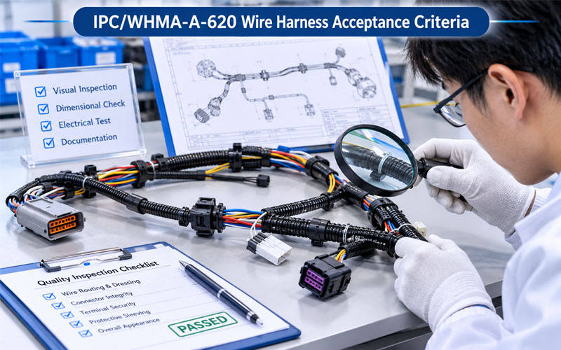
1.What Is IPC/WHMA-A-620?
IPC/WHMA-A-620 is a workmanship and acceptance standard specifically developed for cable and wire harness assemblies.
It provides requirements and acceptance criteria covering manufacturing materials, assembly methods, interconnections, and related workmanship.
Its scope includes areas such as:
- Wire and cable preparation.
- Crimped interconnections.
- Mechanically secured connections.
- Soldered connections.
- Connector and terminal assembly.
- Wire harness routing and assembly.
- Insulation and protective covering.
- Marking and identification.
- Inspection and applicable testing activities.
The standard is used across different manufacturing sectors, including automotive, industrial electronics, telecommunications, aerospace-related supply chains, and other applications requiring controlled cable and harness assembly quality.
1.1 Why does IPC/WHMA-A-620 matter?
Without an agreed workmanship standard, customers and manufacturers may interpret the same physical condition differently.
For example, one inspector may consider a minor insulation irregularity acceptable, while another may reject it. Similar disagreements can occur over terminal positioning, solder appearance, conductor exposure, or mechanical assembly conditions.
IPC/WHMA-A-620 helps reduce this ambiguity by providing a structured reference for evaluating workmanship.
Its practical benefits include:
- More consistent inspection decisions.
- Clearer communication between customers and suppliers.
- Better-defined production workmanship expectations.
- More structured operator and inspector training.
- Improved supplier quality evaluation.
- A common basis for documenting nonconformities.
However, the standard should not be treated as a substitute for product-specific engineering requirements. Drawings, specifications, contracts, and customer requirements must also be considered.
2.Understanding the Three IPC/WHMA-A-620 Product Classes
One of the most important decisions when applying IPC/WHMA-A-620 is selecting the appropriate product class.
The standard defines three product classes based on the intended application and performance expectations.
| Product Class | Description | Typical Application Characteristics |
|---|---|---|
| Class 1 | General Electronic Products | Applications where the main requirement is the function of the completed assembly |
| Class 2 | Dedicated Service Electronic Products | Applications requiring continued performance and extended service life, where uninterrupted operation is desirable but not critical |
| Class 3 | High Performance/Harsh Environment Electronic Products | Applications where continued performance is critical and equipment must function reliably under demanding operating conditions |
2.1 Class 1: General Electronic Products
Class 1 applies to products where the primary requirement is the function of the completed assembly.
The acceptance framework is intended for general electronic applications without the same level of continuous-performance expectations associated with more demanding classes.
This does not mean that quality requirements can be ignored. Materials, workmanship, and product specifications must still meet the applicable acceptance requirements.
2.2 Class 2: Dedicated Service Electronic Products
Class 2 is intended for products where continued performance and extended service life are important.
Equipment downtime is generally undesirable, and the application requires a more demanding level of reliability than typical general electronic products.
Examples may include industrial control systems, commercial electronic equipment, and other applications where reliable long-term operation is expected.
2.3 Class 3: High Performance/Harsh Environment Electronic Products
Class 3 is designed for applications where continued performance or performance on demand is critical.
These products may operate in demanding environments, and equipment failure or downtime may have serious consequences.
Examples can include critical control systems, certain aerospace and defense applications, and life-support-related equipment.
2.4 Who determines the product class?
The applicable class should be agreed upon and documented by the customer and manufacturer.
The user has the ultimate responsibility for identifying the class to which the assembly will be evaluated. If the user does not establish and document the class, the manufacturer may determine it in accordance with the standard.
A manufacturer should not automatically assign Class 3 simply because a harness is used in an automotive or industrial application. The actual application requirements, contractual specifications, and customer agreement must determine the applicable class.
Practical recommendation: Confirm the product class during quotation, technical review, and project launch. Leaving the class undefined can create disagreements during incoming inspection, final acceptance, and customer audits.
3.Wire Preparation and Insulation Acceptance
Wire preparation is one of the first critical stages in wire harness manufacturing.
Incorrect cutting, stripping, or insulation handling can affect the quality of downstream crimping, soldering, and assembly operations.
3.1 Wire cutting and length control
Wire length directly affects harness routing, connector positioning, branch geometry, and installation fit.
Inspection should consider:
Compliance with specified wire lengths and tolerances.
Correct wire identification and conductor size.
Consistent cutting quality.
Absence of unacceptable conductor deformation.
Correct relationship between wire length and branch positioning.
A wire that is too short may create tension at the connector or terminal. Excessive length can cause routing interference, poor installation fit, or unnecessary bundling.
Length acceptance should be based on the approved drawing and applicable product specifications.
3.2 Stripping quality
Stripping removes insulation to expose the conductor for termination.
Poor stripping quality can affect both electrical and mechanical connection performance.
Common conditions requiring inspection include:
- Damaged or cut conductor strands.
- Excessive conductor exposure.
- Insufficient stripping length.
- Remaining insulation or debris in the termination area.
- Insulation damage beyond the intended stripping region.
The acceptance decision should consider the termination method, conductor construction, approved process, and applicable standard requirements.
3.3 Insulation condition
Wire insulation provides electrical protection and helps protect conductors against environmental and mechanical damage.
During inspection, manufacturers should evaluate whether the insulation has been damaged during cutting, stripping, routing, or assembly.
Potential issues include:
- Cuts or deep scratches.
- Cracks or splitting.
- Excessive deformation.
- Heat-related damage.
- Abrasion or pinching.
- Incorrect insulation material.
Any condition that could compromise electrical insulation, mechanical protection, or the specified application performance requires appropriate evaluation.
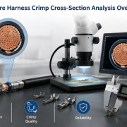
4.Crimping Acceptance Criteria: One of the Most Critical Inspection Areas
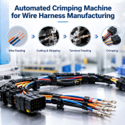
Crimping is a widely used termination method in wire harness manufacturing.
A reliable crimp connection depends on compatibility between the conductor, terminal, tooling, and approved process parameters.
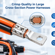
A terminal may appear securely attached but still contain internal defects that affect electrical resistance, mechanical strength, or long-term reliability.
4.1 Visual inspection of crimped terminals
Crimp inspection should evaluate the overall termination condition and relevant features of the terminal.
Common inspection points include:
- Conductor placement within the terminal.
- Insulation support and positioning.
- Crimp wing formation.
- Conductor strand condition.
- Terminal deformation.
- Visible cracks, damage, or irregularities.
- Consistency with the approved crimp design.
The exact acceptance conditions depend on terminal design, conductor construction, applicable product class, and the requirements of the relevant standard.
4.2 Crimp height and width verification
Crimp height and width are important process characteristics for many terminal designs.
Measurements can help determine whether the crimping operation is producing a consistent result within the approved process limits.
However, acceptable dimensions should not be assumed to be universal. They depend on the terminal manufacturer’s specifications, conductor size, tooling design, and applicable engineering requirements.
Manufacturers should establish approved measurement methods and process limits for each relevant terminal and wire combination.
4.3 Pull-force testing
Pull-force testing evaluates the mechanical strength of a wire-to-terminal crimp connection.
It can help identify issues related to:
- Incorrect terminal and wire compatibility.
- Inadequate crimp formation.
- Incorrect tooling settings.
- Conductor damage.
- Process variation.
The applicable test method and acceptance limits should be based on the relevant terminal specification, customer requirements, and applicable standards.
Pull-force testing does not replace visual inspection or dimensional verification. These methods provide different types of quality evidence.
4.4 Why crimp process control matters
A good-looking crimp does not automatically guarantee a reliable connection.
Manufacturers should control the complete termination process, including:
- Correct terminal and wire selection.
- Approved applicator and tooling setup.
- Controlled crimping parameters.
- Regular tooling condition checks.
- Defined inspection methods.
- Documented process verification.
For high-volume production, monitoring crimp process variation can help identify developing problems before they affect a large number of assemblies.
5.Terminal Insertion and Connector Assembly Inspection
A correctly crimped terminal can still create a defective harness if it is not properly inserted into the connector housing.
Terminal insertion is therefore an important inspection point, particularly in automotive and industrial wire harness applications.
5.1 Terminal seating and positioning
Inspectors should verify that terminals are installed in the correct connector cavities and that their positions correspond to the approved wiring diagram.
Relevant checks may include:
- Correct cavity assignment.
- Proper terminal seating.
- Correct terminal orientation.
- Absence of visible terminal displacement.
- Proper engagement of primary locking features.
- Correct secondary locking device position, where applicable.
5.2 Connector locking mechanisms
Many connector systems use primary and secondary locking features to maintain terminal retention.
These mechanisms must be correctly assembled according to the connector design.
Common issues include incomplete terminal insertion, incorrectly positioned secondary locks, damaged locking features, and incompatible terminal-housing combinations.
A terminal that appears to be inserted correctly may still be inadequately retained. Appropriate inspection and verification methods should therefore be defined for the connector system.
5.3 Connector housing condition
Connector housings should be checked for damage that may affect fit, locking, sealing, or electrical connection.
Inspection should consider:
- Cracks or deformation.
- Damaged locking tabs.
- Contamination inside cavities.
- Incorrect connector configuration.
- Damaged seals or sealing interfaces.
- Incorrect identification or orientation.
For sealed connectors, the condition and installation of the relevant sealing components should also be evaluated.
6.Soldering and Mechanically Secured Connections
Although crimping is common in many wire harness applications, soldered and mechanically secured connections are also used in specific assembly designs.
Their acceptance should be evaluated according to the applicable standard requirements and approved process specifications.
6.1 Soldered connection inspection
Soldering quality depends on materials, surface preparation, process temperature, solder application, and joint design.
Inspection may consider:
- Solder coverage and joint formation.
- Conductor condition.
- Evidence of insufficient or excessive solder.
- Solder bridging or unintended connections.
- Heat-related insulation damage.
- Mechanical condition of the completed joint.
Visual appearance alone cannot confirm every aspect of solder joint reliability. Additional verification may be required depending on the application and risk assessment.
6.2 Mechanically secured connections
Mechanically secured connections should be evaluated for correct assembly, retention, and physical condition.
Examples include connections using mechanical fasteners, clamps, or other approved securing methods.
Inspection should verify that the connection follows the specified design and that relevant components are correctly installed.
For assemblies exposed to vibration or mechanical stress, additional application-specific validation may be necessary.
7.Wire Routing, Bundling, and Protective Covering
After termination, wires must be assembled into the required harness configuration.
Incorrect routing or inadequate protection can create installation difficulties and long-term reliability problems.
7.1 Wire routing and branch positioning
Inspection should compare the completed harness against the approved assembly drawing or dimensional requirements.
Important considerations include:
- Overall harness configuration.
- Branch locations and dimensions.
- Wire routing direction.
- Connector orientation.
- Required clearances.
- Correct positioning of clips and retainers.
- Absence of unnecessary tension or twisting.
The finished assembly should maintain the geometry needed for its intended installation.
7.2 Bundling and protective materials
Wire harnesses may use tape, sleeves, corrugated tubing, braided coverings, conduit, or other protective materials.
These materials should be installed according to the design requirements.
Inspection should evaluate:
- Correct protective material.
- Required coverage.
- Secure installation.
- Correct termination and positioning.
- Absence of unacceptable damage.
- Compatibility with the intended application.
7.3 Environmental protection
For applications requiring resistance to moisture, dust, chemicals, temperature, or vibration, additional design-specific requirements may apply.
For example, an IP-rated connector system does not automatically make the entire wire harness assembly compliant with the same ingress protection rating.
The complete assembly configuration, mating interfaces, seals, cable exits, and installation conditions must be considered when evaluating environmental protection.
8.Marking, Labeling, and Product Identification
Correct identification is essential for assembly verification, installation, maintenance, and traceability.
A wire harness may be electrically functional but still fail customer requirements because of incorrect labeling or identification.
Inspection may cover:
- Correct part number.
- Product revision.
- Wire identification.
- Connector identification.
- Label position.
- Marking readability.
- Label adhesion and condition.
- Compliance with customer identification requirements.
For projects requiring traceability, labels may also include batch numbers, serial numbers, QR codes, or other production identification information.
Manufacturers should verify that identification data matches the approved documentation and production records.
9.Electrical Testing and Final Assembly Verification
Workmanship inspection and electrical testing serve different purposes.
A visually acceptable harness may still contain an incorrect electrical connection. Similarly, a harness that passes continuity testing may still contain mechanical or workmanship defects.
A comprehensive acceptance process should combine appropriate inspection and testing methods.
9.1 Continuity testing
Continuity testing verifies whether the intended electrical paths are connected.
It can help identify:
- Open circuits.
- Incorrect wire connections.
- Missing electrical connections.
- Certain terminal contact problems.
Test programs should be developed from the approved wiring diagram and pinout information.
9.2 Short-circuit testing
Short-circuit testing helps identify unintended electrical connections between circuits or conductors.
This is particularly important for multi-circuit harnesses and assemblies with complex connector configurations.
9.3 Insulation resistance and dielectric testing
Depending on the product specification, insulation resistance or dielectric withstand testing may be required.
These tests evaluate electrical insulation performance under defined test conditions.
They should only be applied using approved procedures and suitable equipment, with test voltage, duration, limits, and safety precautions defined by the relevant engineering requirements.
9.4 Final dimensional and visual inspection
Before shipment, the completed harness should be checked against the approved product documentation.
Final inspection may include:
- Overall configuration.
- Connector and terminal assembly.
- Wire lengths and branch dimensions.
- Protective covering.
- Labels and identification.
- Visible workmanship defects.
- Required test records.
The inspection plan should clearly distinguish between visual acceptance, dimensional verification, and electrical testing.
10.How to Apply IPC/WHMA-A-620 in a Practical Quality Control System
Using IPC/WHMA-A-620 effectively requires more than purchasing the standard or referring to it during customer audits.
Manufacturers need to translate applicable requirements into production instructions, inspection criteria, training, and quality records.
10.1 Establish a product-specific inspection plan
The inspection plan should identify:
- Applicable product class.
- Relevant workmanship requirements.
- Critical assembly characteristics.
- Inspection methods.
- Measurement tools and test equipment.
- Acceptance and rejection criteria.
- Required records.
- Nonconformance handling procedures.
Not every requirement applies to every wire harness configuration. The plan should be developed according to the product design, customer requirements, and applicable standard sections.
10.2 Train operators and inspectors
Production personnel should understand the difference between acceptable and unacceptable workmanship.
Training should cover relevant operations such as wire preparation, crimping, terminal insertion, connector assembly, soldering where applicable, and final inspection
IPC offers training and certification programs associated with IPC/WHMA-A-620, including Certified IPC Specialist (CIS) and Certified IPC Trainer (CIT) pathways.
Training can help improve consistency, but certification alone does not guarantee that every production assembly will conform. Process controls, supervision, inspection, and corrective action remain necessary.
10.3 Maintain inspection records and traceability
Inspection records provide evidence that the required checks have been completed.
Depending on the application, useful records may include:
Product part number and revision.
- Production batch or work order.
- Applicable product class.
- Inspection results.
- Crimp verification records.
- Electrical test results.
- Nonconformance and corrective action records.
- Inspector identification.
- Equipment calibration or verification status.
Digital traceability can make it easier to retrieve production information and investigate quality issues.
10.4 Define inspection frequency separately
An important limitation of IPC/WHMA-A-620 is that it does not independently define the frequency of in-process inspection or final product inspection.
Manufacturers and customers should establish inspection frequency through an appropriate quality plan, taking into account process risk, production volume, product complexity, and customer requirements.
This means that simply stating “manufactured according to IPC/WHMA-A-620” does not fully describe the inspection sampling plan or every quality control activity.
The manufacturer should clarify how the standard is applied and what additional controls are included in the production process.
11.Choosing the Correct IPC/WHMA-A-620 Revision
Standards are periodically revised to reflect updated industry practices and technical requirements.
As of November 2026, IPC/WHMA-A-620F, published in October 2025, is the current revision listed in IPC’s revision history.
However, manufacturers should not assume that the newest revision automatically applies to every existing project.
The applicable revision should be confirmed through customer drawings, purchase specifications, contracts, quality agreements, and other controlled project documentation.
Before changing to a newer revision, manufacturers should consider:
- Whether the customer requires a specific revision.
- Whether the purchase order references an older edition.
- Whether inspection instructions need updating.
- Whether training materials need revision.
- Whether acceptance criteria or documentation practices are affected.
- Whether customer approval is required for the transition.
For international projects, the language version should also be considered. The applicable official standard should be consulted whenever detailed acceptance decisions are required.
How FPIC Supports Wire Harness Quality and Manufacturing Consistency
Applying an acceptance standard effectively requires a manufacturing system that connects engineering specifications, production processes, and quality verification.
FPIC has 23 years of experience in connector and cable assembly manufacturing. For customized wire harness projects, technical communication and early review of product requirements help align design specifications with practical manufacturing and inspection considerations.
Important areas of project evaluation include:
- Wire, terminal, and connector specification review.
- Manufacturing process and assembly feasibility.
- Crimping and terminal insertion quality control.
- Electrical testing requirements.
- Product identification and traceability.
- Customer-specific inspection and acceptance requirements.
For OEM projects, defining the applicable IPC/WHMA-A-620 revision and product class at the beginning of the project can help establish clearer quality expectations between the customer and manufacturer.
Conclusion
IPC/WHMA-A-620 provides a recognized framework for evaluating cable and wire harness workmanship, but effective implementation requires more than a final visual inspection.
Manufacturers need to consider product classification, wire preparation, crimping, terminal insertion, soldering, routing, protective covering, identification, and electrical testing.
The key is to translate applicable standard requirements into clear production controls, inspection criteria, operator training, and traceable quality records.
By establishing these controls and agreeing on the applicable product class and standard revision with customers, wire harness manufacturers can improve inspection consistency, reduce acceptance disputes, and support more reliable product quality.
FAQ
What is IPC/WHMA-A-620 used for?
IPC/WHMA-A-620 provides requirements and acceptance criteria for the manufacture and inspection of cable and wire harness assemblies. It covers materials, workmanship, crimped and soldered connections, mechanically secured connections, and related assembly activities.
What are the three IPC/WHMA-A-620 classes?
The standard defines Class 1 for General Electronic Products, Class 2 for Dedicated Service Electronic Products, and Class 3 for High Performance/Harsh Environment Electronic Products. The applicable class should be agreed upon and documented by the customer and manufacturer.
Does IPC/WHMA-A-620 specify crimping quality requirements?
Yes. It addresses crimped interconnections and related workmanship acceptance. Manufacturers should use the applicable requirements together with terminal specifications, approved tooling information, and customer-specific requirements.
Does IPC/WHMA-A-620 require 100% electrical testing?
The standard does not independently establish a universal 100% electrical testing requirement for every harness. Inspection and testing frequency should be defined through the applicable customer requirements and quality control plan.
Is IPC/WHMA-A-620 the same as IATF 16949?
No. IPC/WHMA-A-620 is a cable and wire harness workmanship and acceptance standard. IATF 16949 is an automotive quality management system standard that addresses broader organizational and manufacturing quality management requirements.
What is the latest IPC/WHMA-A-620 revision?
As of November 2026, IPC/WHMA-A-620F, published in October 2025, is the latest revision listed in IPC’s revision history. However, the revision required for a specific project should follow the applicable customer and contractual documentation.
Does IPC/WHMA-A-620 replace customer-specific specifications?
No. Customer drawings, technical specifications, contracts, and other applicable requirements must also be considered. The applicable acceptance criteria should be agreed upon and documented before production and inspection.
How can manufacturers improve IPC/WHMA-A-620 compliance?
Manufacturers can establish a product-specific inspection plan, train operators and inspectors, control crimping and assembly processes, maintain calibrated or verified equipment, document inspection results, and review nonconformities through a structured corrective action process.
Looking for a wire harness manufacturer with structured quality control?
FPIC supports customized wire harness and cable assembly projects with engineering coordination, manufacturing process control, and application-based quality verification.
Share your drawings, BOM, product specifications, and applicable IPC/WHMA-A-620 requirements with our team to discuss your project.
Resources
- IPC/WHMA-A-620 – Requirements and Acceptance for Cable and Wire Harness Assemblies
Official IPC information about the standard, its scope, and the latest published revision. - IPC Standards Revision Table
Official revision history showing the publication status of IPC/WHMA-A-620F and previous editions. - WHMA – Understanding the Foundations of IPC/WHMA-A-620
An industry overview explaining the role of IPC/WHMA-A-620 in cable and wire harness workmanship, training, and quality consistency. - WHMA – OEM and EMS Resources
Explains how the standard supports consistent acceptance requirements and quality communication between OEMs, EMS providers, and manufacturing suppliers. - IPC/WHMA-A-620F – Official Standard Information
Publication and document information for the 2025 F revision of the cable and wire harness assembly acceptance standard.