Why Controlled Work Instructions Matter in Wire Harness Production
Wire harness manufacturing requires operators to convert engineering data into a physical product through a sequence of cutting, stripping, crimping, soldering, connector insertion, routing, protection, inspection, and testing operations.
Each operation may appear straightforward when considered individually. The difficulty comes from ensuring that every operator, workstation, production shift, and repeat order follows the same approved requirements.
A typical custom assembly may involve:
- Multiple wire gauges and colors
- Different terminal and seal combinations
- Similar connector housings
- Detailed cavity assignments
- Branch dimensions and routing requirements
- Crimping and soldering specifications
- Sleeves, tapes, conduits, labels, and ties
- Project-specific testing
- Customer-specific acceptance criteria
Without controlled work instructions, operators may rely on printed drawings, handwritten notes, memory, or informal training. This increases the risk of outdated revisions, incorrect materials, inconsistent processing, and undocumented production changes.
A controlled instruction system establishes one approved manufacturing reference for the complete production process:
Engineering Release → Material Verification → Wire Processing → Assembly → First-Article Approval → Electrical Testing → Final Inspection
The objective is not merely to create more documentation. It is to ensure that the right information reaches the right workstation at the right time.
What Are Controlled Work Instructions?
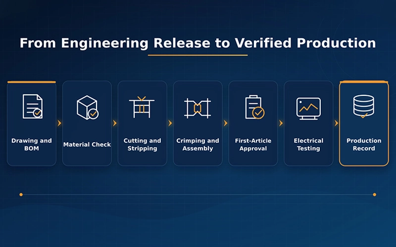
Controlled work instructions are approved manufacturing documents that define how a product must be produced, inspected, tested, and recorded.
For a custom wire harness, they may include:
- Product number
- Customer part number
- Drawing revision
- BOM revision
- Wire list
- Connector cavity table
- Material specifications
- Processing dimensions
- Tooling requirements
- Assembly sequence
- Inspection checkpoints
- First-article requirements
- Electrical test program
- Packaging instructions
A controlled instruction should also identify:
- Who approved the document
- When it became effective
- Which production order it applies to
- Whether an older version has been replaced
- How engineering changes are communicated
Modern wire harness manufacturing software increasingly generates instructions directly from engineering data. Zuken describes its work-instruction tools as a method for creating, releasing, and managing assembly packages using information already captured during harness design. This reduces repeated manual document preparation and helps maintain consistency between engineering and manufacturing.
Controlled instructions may be provided as:
- Printed process sheets
- Controlled PDF documents
- Workstation screens
- MES work orders
- Digital step-by-step assembly tasks
- Visual formboard guidance
The format can vary. The critical requirement is that the content remains current, approved, understandable, and connected to the correct product revision.
Why Uncontrolled Instructions Create Quality Risk
Many harness defects are not caused by a lack of operator effort. They result from incomplete, outdated, or inconsistent production information.
Outdated Drawings
An operator may continue using a previously printed drawing after an engineering change has modified:
- Wire length
- Connector cavity
- Terminal model
- Branch dimension
- Label position
- Test requirement
The finished product may appear acceptable but no longer match the released design.
Inconsistent BOM Information
The drawing, BOM, wire list, and workstation material list may not always remain synchronized.
This can result in:
- Wrong terminals
- Missing seals
- Incorrect wire specifications
- Unapproved connector substitutions
- Incorrect protective materials
Manual Transcription Errors
Production personnel may copy data from drawings into:
- Cutting-machine programs
- Crimping instructions
- Connector insertion tables
- Label files
- Electrical test programs
Each manual transfer introduces another opportunity for error.
Reliance on Personal Experience
Experienced operators often develop efficient working methods. However, undocumented knowledge creates risk when:
- The operator changes position
- A new employee takes over
- Production moves to another shift
- The same product is repeated months later
- A customer changes one requirement
The manufacturing process should be supported by controlled information rather than depending entirely on individual memory.
1. Drawing and BOM Revision Control
The first purpose of a controlled instruction is to establish the correct product definition.
The production floor should be able to identify:
- Current drawing revision
- Approved BOM revision
- Applicable wire-list version
- Effective engineering-change date
- Work orders affected by the change
- Obsolete documents that must not be used
Zuken’s revision-management tools compare design versions and record changes in graphical and textual formats. Its manufacturing environment also maintains links between BOM and wire reports so that wire lengths, end treatments, and related material information remain synchronized.
Information That Should Be Version-Controlled
| Document or Data Set | Typical Content |
| Harness drawing | Dimensions, branches, routing, connector orientation |
| BOM | Wires, terminals, housings, seals, sleeves, labels, accessories |
| Wire list | Circuit, from-to points, cavity numbers, wire size, color, length |
| Process instruction | Cutting, stripping, crimping, soldering, assembly |
| Inspection plan | Dimensions, workmanship, crimp checks, checkpoints |
| Test program | Continuity, miswiring, insulation, resistance, limits |
| Packaging instruction | Coiling, protection, labeling, shipment requirements |
A change to a wire size may also require changes to:
- Terminal selection
- Crimp tooling
- Strip length
- Crimp height
- Pull-force criteria
- Electrical test limits
- BOM cost
Effective revision control therefore considers the complete manufacturing impact of the change.
2. Verifying Wires, Terminals, and Connectors
A work instruction should clearly identify every material needed for the assembly.
Important information may include:
- Internal part number
- Manufacturer part number
- Material description
- Approved supplier
- Wire gauge
- Wire color
- Insulation type
- Terminal model
- Connector housing
- Seal and cavity plug
- Secondary lock
- Sleeve or conduit
- Label
- Quantity per assembly
Wire Verification
Operators should confirm:
- Correct wire specification
- Correct conductor size
- Correct color
- Correct insulation or jacket
- Correct reel or material lot
- Correct marking requirement
Terminal Verification
Terminals that appear similar may have different:
- Wire-size ranges
- Material thicknesses
- Plating
- Contact geometry
- Seal compatibility
- Crimp dimensions
The instruction should therefore use exact part numbers rather than only a general description such as “female terminal.”
Connector Verification
The instruction should identify:
- Housing part number
- Number of positions
- Keying
- Color
- Secondary lock
- Mating interface
- Required seals and plugs
- Connector orientation
Material scanning through ERP, WMS, or MES can help confirm that the issued component matches the production order, but the system depends on accurate master data and correct labels.
3. Cutting and Stripping Instructions
Wire processing instructions should define the parameters necessary to produce a repeatable prepared wire.
Typical cutting and stripping data includes:
- Wire part number
- Cut length
- Length tolerance
- Strip length at each end
- Partial-strip or full-strip requirement
- Quantity
- Wire marking
- Machine program
- Blade or tooling requirement
Why Cut Length Matters
Wire length affects:
- Overall harness dimensions
- Branch position
- Connector reach
- Routing
- Mechanical tension
- Bend radius
- Installation fit
A difference of only a few millimeters can become significant in compact equipment or multi-branch assemblies.
Why Strip Length Matters
Incorrect stripping can cause:
- Insufficient conductor engagement
- Excessive exposed strands
- Insulation inside the conductor crimp
- Weak insulation support
- Damaged conductor strands
- Poor soldering preparation
The instruction should define both the nominal value and the applicable tolerance.
For automated equipment, the machine program should be linked to the product or operation number. Operators should not rely only on manually entering values from a printed sheet.
4. Controlled Crimping Instructions
Crimping is one of the most important processes in wire harness production because it creates the mechanical and electrical connection between the terminal and conductor.
A controlled crimping instruction may include:
- Wire specification
- Terminal part number
- Seal part number
- Crimping machine
- Applicator or die number
- Crimp height
- Crimp width
- Pull-force requirement
- Strip length
- Wire position
- Seal position
- Inspection frequency
- Reference images
IPC/WHMA-A-620E covers materials, methods, tests, and acceptability criteria for crimped, mechanically secured, and soldered cable and harness interconnections. IPC also emphasizes process-control methodology as the basis for maintaining consistent manufacturing quality.
Crimping Checks May Include
- Visual appearance
- Conductor brush
- Insulation position
- Terminal deformation
- Crimp height
- Pull force
- Cross-section analysis
- Seal position
- Locking-lance condition
A crimp that appears visually acceptable may still have an incorrect internal compression condition. For this reason, appearance inspection should be combined with measurable process controls according to the product requirement.
5. Soldering and Welding Instructions
Some assemblies include soldered joints, shield terminations, or welded splices.
The work instruction should define:
- Wire preparation
- Strip length
- Conductor arrangement
- Soldering temperature
- Heating duration where applicable
- Solder material
- Flux requirements
- Joint protection
- Heat-shrink size and location
- Acceptance criteria
For ultrasonic or other welding operations, instructions may include:
- Wire combination
- Conductor cross-sectional area
- Weld size
- Machine program
- Tooling
- Splice orientation
- Protective covering
Zuken’s Harness Builder recognizes splicing and welding as part of the harness manufacturing definition and can produce machine outputs and detailed manufacturing information for welded connections.
The instruction must also distinguish between:
- Approved process parameters
- Operator-adjustable settings
- Settings that require engineering authorization
Uncontrolled adjustments may create variation that is difficult to detect during final inspection.
6. Connector Insertion and Assembly Sequence
After wire preparation, the conductors must be assembled into connectors and routed into the finished harness.
Instructions should define:
- Connector orientation
- Cavity number
- Circuit number
- Wire color
- Terminal insertion direction
- Seal position
- Secondary-lock operation
- Retention check
- Branch-routing sequence
Visual Cavity Guidance
Connector cavity diagrams are often more reliable than long text descriptions, especially when:
- Connectors contain many positions
- Similar housings are used
- Several wire colors are repeated
- The product has multiple variants
Digital assembly systems can display the exact component position within a harness drawing or digital formboard and guide the technician through each task using text, images, videos, and links.
Routing and Protection Instructions
The work instruction should also specify:
- Main-trunk direction
- Branch dimensions
- Tape starting and ending points
- Sleeve length
- Conduit position
- Tie location
- Label position
- Bend-radius requirements
- Shield termination
- Grounding point
- Strain relief
Sequence matters. Installing a sleeve or secondary lock too early may prevent later inspection or rework.
7. First-Article Confirmation
The first article verifies that engineering data, materials, equipment, tooling, assembly instructions, and test programs have been correctly transferred into production.
Automation does not remove this need. A machine can reproduce an incorrect setup as consistently as a correct one.
First-Article Material Checks
- Wire and cable
- Terminal
- Connector
- Seal
- Sleeve or conduit
- Label
- Other accessories
First-Article Process Checks
- Cut length
- Strip length
- Crimp height
- Pull force
- Solder or weld condition
- Terminal orientation
- Seal position
First-Article Assembly Checks
- Cavity assignment
- Branch dimensions
- Routing
- Tape and sleeve positions
- Label content
- Overall appearance
First-Article Electrical Checks
- Continuity
- Open circuits
- Short circuits
- Miswiring
- Insulation resistance
- Withstand voltage where required
The result should be associated with:
- Product number
- Drawing revision
- BOM revision
- Work order
- Material lots
- Machine and tooling
- Operator
- Inspector
- Test program
- Approval date and time
The batch should proceed only after the defined approval has been completed.
8. Abnormality Reporting and Production Feedback
Controlled instructions should tell operators not only how to produce the product, but also what to do when the process does not match expectations.
Examples include:
- Wire insulation cannot be stripped cleanly
- Terminal does not fit the applicator
- Crimp height is outside the limit
- Connector cavity diagram conflicts with the wire list
- Material part number differs from the BOM
- Branch dimension cannot be achieved
- Electrical test repeatedly fails
- A drawing note is unclear
The Correct Response Is Not Informal Adjustment
Operators should not independently:
- Substitute a component
- Change a cut length
- Modify a crimp setting
- Skip an inspection
- Reassign a connector cavity
- Change a test limit
Instead, the abnormality should be recorded and reviewed through the appropriate engineering or quality process.
Useful Abnormality Records
- Product and work order
- Operation
- Problem description
- Quantity affected
- Material involved
- Equipment and tooling
- Immediate containment
- Photographs
- Engineering response
- Approved disposition
- Rework or retest requirement
This creates a production feedback loop and prevents the same issue from being resolved differently by different operators.
9. Electrical Testing and Inspection Records
The work instruction should define which tests apply, how they are performed, and how the results are recorded.
Typical electrical tests include:
- Continuity
- Open-circuit detection
- Short-circuit detection
- Miswiring verification
- Insulation resistance
- Withstand voltage
- Contact resistance
- Functional testing
Test Records Should Identify
- Product number
- Work order
- Drawing revision
- Test-program revision
- Tester
- Test fixture
- Date and time
- Operator
- Pass or fail result
- Failure code
- Retest history
The test program must match the correct wire list and connector-cavity definition.
A product can pass an obsolete or incomplete test program. Therefore, test-program version control is as important as drawing control.
Zuken’s 2026 manufacturing updates include direct integration with Cirris and Weetech testers, illustrating the industry’s movement toward linking approved engineering data with shop-floor testing and reducing manual test-program preparation.
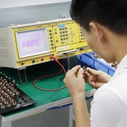
FPIC’s documented quality equipment includes cable-harness testers, contact-resistance equipment, temperature-rise testing, and withstand-voltage and insulation testers.
10. How Process Changes Reach the Production Floor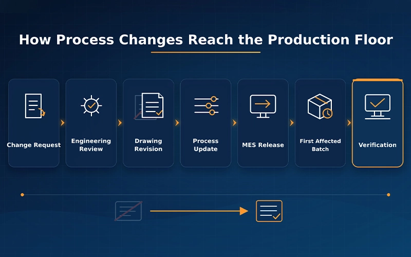
Engineering changes are one of the most common points of failure in controlled manufacturing.
A change may originate from:
- Customer drawing update
- Material discontinuation
- Connector replacement
- Production improvement
- Quality corrective action
- Test-requirement change
- Cost-reduction project
- Regulatory update
A Controlled Change Process Should Include
- Change request
- Technical evaluation
- Customer approval where required
- Drawing and BOM update
- Process-impact review
- Work-instruction revision
- Machine-program update
- Test-program update
- Effective-date definition
- Production-floor release
- Obsolete-document withdrawal
- Verification of the first affected batch
ISA-95 defines information exchange between enterprise functions and manufacturing operations, including MES-level activities. Its purpose includes reducing the risk, cost, and errors associated with transferring information between business and manufacturing systems.
In practice, PLM can manage the approved engineering revision, while MES distributes the applicable instruction to the workstation.
This helps answer:
- Which orders use the old version?
- Which order is the first to use the new version?
- Have the machine and test programs been updated?
- Have operators received the revised instruction?
- Were obsolete copies removed?
- Was the changed product revalidated?
Paper Instructions Versus Controlled Digital Instructions
| Comparison Area | Uncontrolled Paper Documents | Controlled Digital Instructions |
| Revision status | May remain in use after a change | Current revision can be released centrally |
| BOM synchronization | Separate sheets may conflict | Engineering data can remain linked |
| Operator guidance | Text and static images | Step-by-step text, images, video, and visual location |
| Process sequence | Operator manually follows the page | System can control and record task order |
| Change distribution | Requires replacing printed copies | Updated instructions can reach relevant stations |
| Completion records | Often manually signed | Task status can be recorded electronically |
| Abnormality feedback | May rely on verbal communication | Issue can be linked to product and operation |
| Test connection | Program may be prepared separately | Approved data can feed compatible test systems |
| Traceability | Paper records require manual retrieval | Records can be linked to work order or batch |
Digital instructions do not automatically create a controlled process. They still require:
- Approved engineering data
- User access control
- Revision management
- Correct workstation assignment
- Data backup
- Training
- Change authorization
A poorly controlled screen can create the same risk as an outdated paper document.
How PLM, ERP, MES, and WMS Support Instructions
Controlled production normally depends on several connected systems.
| System | Role |
| PLM | Manages drawings, BOMs, specifications, and engineering changes |
| ERP | Manages customer orders, purchasing, planning, and production demand |
| WMS | Controls material locations, lots, and production issue |
| MES | Releases work instructions, records production activities, and tracks status |
| QMS | Manages inspections, nonconformities, and corrective actions |
| Tester software | Runs approved electrical test programs and stores results |
ISA-95 describes MES and related systems as part of the manufacturing-operations layer between physical production control and enterprise business systems.
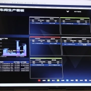
FPIC’s intelligent manufacturing environment includes PLM, ERP, MES, WMS, QMS, SCADA, BI, and related management platforms.
The value of these systems is not the number of software platforms. It is their ability to maintain one controlled information path from engineering approval through manufacturing and testing.
FPIC’s Controlled Wire Harness Production Process
FPIC combines engineering-data control, automated wire processing, first-article confirmation, inspection, electrical testing, and production records for customized cable assembly projects.
Engineering Review
Customer drawings, BOMs, wire lists, samples, applications, and testing requirements are reviewed before production release.
Controlled Product Data
Approved drawings, component specifications, process requirements, and revisions can be managed through PLM and released into production systems.
Material Verification
Wire, terminals, connectors, seals, sleeves, labels, and other components are checked against the approved BOM and production order.
Automated Wire Processing
FPIC’s equipment documentation includes automatic wire cutting and stripping, servo crimping, terminal-processing machines, and integrated cutting, stripping, crimping, and tin-dipping equipment.
Controlled Manual Assembly
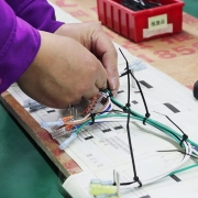
Connector insertion, routing, soldering, protective-material installation, and other assembly operations are performed according to product-specific requirements.
First-Article Confirmation
The initial product is checked for:
- Materials
- Processing dimensions
- Crimping
- Connector configuration
- Branch dimensions
- Workmanship
- Electrical performance
100% Electrical Testing
Finished products are tested according to the approved circuit and project-specific requirements.
Production Records
MES and related systems support the recording of production, inspection, testing, and order status information.
Customer Benefits of Controlled Work Instructions
1. Lower Revision Risk
The production team uses the correct drawings, BOM, process instructions, and test requirements.
2. More Consistent Processing
Operators follow defined cutting, stripping, crimping, soldering, and assembly parameters.
3. Faster Operator Training
New operators can follow structured steps rather than depending entirely on verbal explanation.
4. Better First-Pass Yield
Clear material, cavity, routing, and inspection information helps prevent errors before final testing.
5. Faster Engineering-Change Implementation
Revised requirements can be released through a controlled system and connected to the affected production orders.
6. Stronger Repeat-Order Consistency
The manufacturer can retrieve the approved process used for earlier production rather than recreating it from memory.
7. Better Quality Evidence
First-article results, inspections, electrical tests, and production records provide objective manufacturing evidence.
8. More Efficient Failure Investigation
The manufacturer can compare the product revision, material lots, machine programs, process records, and test results associated with the affected batch.
Questions Buyers Should Ask a Wire Harness Supplier
When evaluating a custom cable assembly manufacturer, customers should ask:
- How are drawings and BOM revisions controlled?
- How does the production floor identify the current version?
- How are wires, terminals, connectors, and seals verified?
- Are cutting, stripping, and crimping parameters documented?
- How are connector cavity assignments communicated?
- What is included in first-article approval?
- How are abnormalities and rework recorded?
- Is every finished harness electrically tested?
- Is the test-program revision linked to the product revision?
- How are engineering changes released to production?
- Can obsolete instructions be blocked?
- Can manufacturing and test records be retrieved by batch?
These questions provide a clearer picture of production control than simply asking whether the factory has automated machines.
Conclusion
Controlled work instructions are essential because wire harness quality depends on the correct execution of many connected manufacturing steps.
A reliable instruction system should control:
- Drawings and BOM revisions
- Wire, terminal, and connector selection
- Cutting and stripping dimensions
- Crimping parameters
- Soldering and welding requirements
- Connector insertion and routing
- First-article confirmation
- Abnormality feedback
- Electrical testing
- Inspection records
- Engineering changes
The goal is not to remove operator skill. It is to give skilled operators accurate, current, and understandable production information.
The strongest manufacturing process connects:
Approved Engineering Data → Controlled Instructions → Verified Materials → Validated Processing → First-Article Approval → 100% Electrical Testing → Traceable Records
For customers, this creates more consistent products, faster change implementation, better repeat-order control, and stronger evidence that every batch was produced according to the approved requirements.
FAQ
1. What is a controlled wire harness work instruction?
It is an approved manufacturing document that defines the materials, processes, assembly sequence, inspection points, tests, and records required to produce a specific assembly.
2. Why must drawings and BOMs have revision control?
Revision control ensures that production uses the latest approved design and prevents outdated materials, dimensions, or wiring configurations from being manufactured.
3. What information should a crimping instruction include?
It may include the wire and terminal combination, machine, applicator, strip length, crimp height, pull-force requirement, seal position, and inspection criteria.
4. Why is first-article confirmation necessary?
It verifies that the correct materials, tooling, machine programs, dimensions, assembly configuration, and test program are in place before the full batch proceeds.
5. Can digital instructions replace operator training?
No. Digital instructions improve consistency and clarity, but operators still require process training, equipment authorization, and workmanship knowledge.
6. How should production abnormalities be handled?
They should be recorded, contained, and reviewed by authorized engineering or quality personnel before the operator changes any material, parameter, assembly sequence, or test requirement.
7. Why should the test-program revision be recorded?
A harness may pass an outdated or incomplete test program. Linking the test version to the product revision confirms that the correct electrical requirements were applied.
8. How does MES support work-instruction control?
MES can distribute the applicable instruction, identify the product and work order, record task completion, manage inspection status, and link test results with the manufacturing record.
Turn Approved Engineering Data into Consistent Production
FPIC supports custom wire harness projects from drawing and BOM review through controlled material preparation, automated wire processing, first-article confirmation, 100% electrical testing, and traceable batch production.
Send us your drawings, wire list, BOM, connector specifications, test requirements, expected quantities, and delivery plan for engineering evaluation.
Email: info@sz-fpi.com
Resources
- Zuken — Intelligent Manufacturing Work Instructions
Explains how engineering data can be used to create, release, and manage manufacturing instruction packages, reducing manual document preparation and improving consistency. - Zuken — Digital Work Instructions for Harness Manufacturing
Describes step-by-step digital guidance, visual component location, centralized task data, and progress recording for wire harness assembly. - Zuken — Harness Builder 2026 Manufacturing Updates
Covers digital work instructions, BOM and wire-list reporting, and direct connections with Cirris and Weetech electrical testers. - IPC — IPC/WHMA-A-620E
Defines industry requirements and acceptance criteria for cable and wire harness manufacturing, including crimped, mechanically secured, and soldered interconnections. - ISA — ISA-95 Enterprise-Control System Integration
Provides a framework for exchanging information between enterprise systems and manufacturing operations, including MES-level production management.