Environmental Testing for Wire Harness Assemblies
Wire harness assemblies are often installed in environments that place continuous demands on their electrical connections and protective materials. Automotive wiring may experience temperature fluctuations, engine vibration, moisture, and road salt. Industrial equipment wiring may be exposed to oil, chemicals, dust, and mechanical movement. Outdoor energy storage systems may face sunlight, rain, humidity, and seasonal temperature changes.
Under these conditions, a wire harness must do more than provide electrical continuity during initial inspection. It must maintain its electrical, mechanical, and protective performance throughout its intended service life.
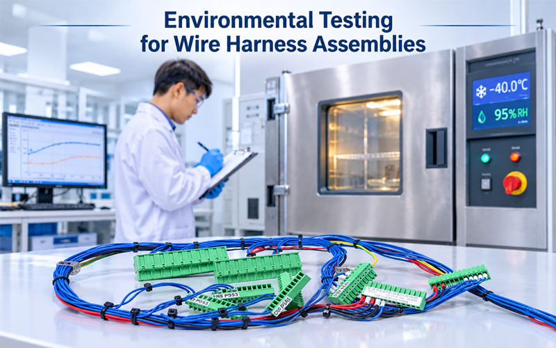
Environmental testing helps engineers evaluate how a wire harness responds to these external stresses. By simulating relevant operating conditions in a controlled test environment, manufacturers can identify potential weaknesses in wire insulation, terminal connections, connector seals, protective coverings, and assembly structures before products enter regular production or field service.
However, environmental testing is not simply a checklist of laboratory procedures. The appropriate tests, severity levels, durations, and acceptance criteria depend on the application, product design, customer requirements, and applicable standards.
This article explains the major environmental tests used for wire harness assemblies and how manufacturers can apply them to improve product reliability.
1. Why Environmental Testing Matters for Wire Harness Assemblies
A wire harness may pass initial continuity and insulation checks but still experience problems after prolonged exposure to environmental stress.
For example, repeated temperature changes can affect material dimensions and sealing interfaces. Moisture may contribute to corrosion or insulation deterioration. Vibration can gradually damage conductors and terminal connections. Chemical exposure may cause insulation swelling, cracking, or loss of flexibility.
Environmental testing helps manufacturers evaluate these potential risks before they become field failures.
Key objectives include:
- Verifying that wire and insulation materials are suitable for the intended environment.
- Evaluating connector sealing and moisture protection.
- Identifying corrosion risks at terminals and contact interfaces.
- Assessing mechanical durability under vibration and shock.
- Checking material resistance to chemicals, oils, and cleaning agents.
- Evaluating performance under temperature fluctuations and outdoor exposure.
- Confirming that electrical performance remains within defined acceptance limits.
Environmental validation is especially important for customized wire harnesses because the combination of wire, connector, terminal, protective sleeve, sealing structure, and installation method may differ from one project to another.
2. Temperature Testing: High and Low Temperature Performance
Temperature is one of the most important environmental factors affecting wire harness reliability.
Different materials respond differently to heat and cold. Excessive temperature may accelerate insulation aging, reduce material strength, or affect connector components. Low temperatures may make certain insulation materials less flexible and more susceptible to cracking during bending.
Temperature testing should therefore consider the complete assembly rather than only the wire’s rated temperature.
2.1 High Temperature Testing
High temperature testing evaluates whether a wire harness can maintain its intended performance under elevated thermal conditions.
Potential risks include:
- Insulation softening or deformation.
- Accelerated material aging.
- Reduced flexibility.
- Changes in connector housing dimensions.
- Degradation of sealing materials.
- Increased contact resistance under certain conditions.
- Damage to protective coverings or cable jackets.
The test temperature and exposure duration should reflect the intended operating environment and the applicable product specification.
For assemblies installed near motors, power electronics, heaters, or other heat-generating components, engineers should also consider localized temperature exposure rather than relying only on the general ambient temperature.
2.2 Low Temperature Testing
Low temperature testing evaluates the ability of the assembly to withstand cold conditions without unacceptable material or functional deterioration.
Potential failure modes include:
- Insulation cracking.
- Reduced cable flexibility.
- Damage during installation or bending.
- Seal hardening.
- Connector housing brittleness.
- Increased mechanical stress at termination points.
For applications involving movement, low-temperature exposure may need to be followed by a defined bending or flexing evaluation.
A harness that remains electrically functional while stationary may still fail when subjected to mechanical movement at low temperatures.
2.3 Temperature Cycling Testing
Temperature cycling exposes a wire harness to repeated transitions between defined high and low temperature conditions.
The purpose is to evaluate the effects of repeated thermal expansion and contraction on materials and interfaces.
Potential risks include:
- Loosening or deterioration of connection interfaces.
- Cracking of insulation or protective materials.
- Changes in sealing performance.
- Stress concentration near connector exits.
- Damage caused by differences in thermal expansion between materials.
Temperature cycling is particularly useful for assemblies containing multiple materials, such as copper conductors, polymer insulation, metal terminals, plastic connector housings, and elastomeric seals.
Important distinction: Temperature cycling and thermal shock are not interchangeable. Thermal shock generally involves more rapid temperature transitions and a different stress profile. The selected method should match the intended validation objective.
3. Humidity and Moisture Resistance Testing
Moisture can affect both electrical performance and material durability.
Wire harness assemblies may encounter high humidity, condensation, rainwater, washing processes, or moisture trapped inside equipment enclosures.
If moisture reaches unprotected conductive areas, it may contribute to corrosion, leakage current, and unstable electrical connections.
3.1 Humidity Testing
Humidity testing evaluates the response of an assembly to elevated moisture conditions over a defined period.
Depending on the test method, exposure may involve controlled temperature and relative humidity, with or without condensation.
Engineers should evaluate:
- Insulation resistance.
- Electrical continuity.
- Terminal and contact corrosion.
- Connector sealing condition.
- Material swelling or deformation.
- Changes in electrical connection performance.
Humidity testing can help reveal weaknesses in insulation materials, connector seals, and protective structures.
3.2 Condensation and Moisture Exposure
Condensation can occur when temperature changes cause moisture in the surrounding air to form liquid water on cooler surfaces.
This is particularly relevant to equipment operating outdoors or moving between environments with different temperatures.
Potential risks include:
- Moisture accumulation inside connector housings.
- Corrosion of terminals and contacts.
- Water entry through cable interfaces.
- Deterioration of sealing materials.
- Intermittent electrical faults.
A suitable validation plan should consider the actual enclosure design, cable entry direction, connector mating condition, and installation orientation.
3.3 Water Ingress Testing
Water ingress testing evaluates the ability of a defined enclosure or assembly to resist water entry under specified conditions.
It is particularly important for outdoor equipment, automotive systems, industrial machinery, and energy storage installations.
The test method and acceptance criteria should correspond to the intended ingress protection requirements.
An IP rating should not be interpreted as a universal guarantee of waterproof performance under every installation or operating condition. The complete assembly configuration, including connector mating, cable entry, seals, and installation details, must be considered.
4. IP67 and IP68 Testing for Sealed Wire Harness Assemblies
For applications exposed to dust and water, ingress protection is an important part of connector and wire harness validation.
The IEC 60529 IP Code provides a framework for classifying the degree of protection provided by enclosures against access to hazardous parts, solid foreign objects, and water ingress.
For road vehicles, ISO 20653 is another relevant reference for degrees of protection provided by electrical equipment against foreign objects, water, and access.
4.1 IP67 Testing
IP67 indicates:
- 6: Dust-tight protection under the specified test conditions.
- 7: Protection against harmful effects of temporary immersion in water under the specified test conditions.
For a wire harness assembly, the relevant connector and cable interfaces should be evaluated in their intended configuration.
Important inspection points include:
- Connector mating condition.
- Seal installation.
- Cable diameter compatibility.
- Rear sealing and cable entry structure.
- Housing damage or deformation.
- Water ingress after testing.
4.2 IP68 Testing
IP68 indicates protection against continuous immersion under conditions specified by the manufacturer and agreed with the relevant testing requirements.
Unlike IPX7, the IPX8 immersion conditions are not defined by one universal depth and duration for all products.
The test conditions must be clearly specified, including relevant immersion depth, duration, and assembly configuration.
4.3 What Should Be Checked After Ingress Testing?
After water ingress testing, engineers may perform:
- Visual inspection for moisture inside the assembly.
- Connector and seal condition checks.
- Continuity testing.
- Insulation resistance testing, where appropriate.
- Contact resistance evaluation, if required by the project.
- Functional verification.
For custom cable assemblies, testing only an individual connector component may not fully represent the assembled product. Cable entry seals, backshells, overmolding, and mating interfaces can all affect the final result.
5. Salt Spray and Corrosion Resistance Testing
Corrosion is a major reliability concern for wire harnesses used in automotive, marine, outdoor, and industrial environments.
Metal terminals and contacts may be exposed to moisture, salt, and corrosive substances. Over time, corrosion can affect conductive surfaces and increase the risk of unstable electrical connections.
5.1 Salt Spray Testing
Salt spray testing exposes test samples to a controlled salt-containing environment to evaluate their resistance to corrosion.
Commonly referenced methods include ASTM B117 and ISO 9227.
Depending on the project, testing may focus on:
- Terminal plating.
- Exposed metal surfaces.
- Connector contacts.
- Fasteners and metallic accessories.
- Corrosion behavior around conductive interfaces.
The test duration and acceptance criteria should be established according to the applicable material specification and customer requirements.
5.2 Common Corrosion-Related Risks
Potential issues include:
- Corrosion of terminal surfaces.
- Degradation of protective plating.
- Increased contact resistance.
- Corrosion near damaged insulation.
- Deterioration of metallic connector components.
The actual failure risk depends on the metal materials, plating system, environmental exposure, electrical loading, and sealing design.
5.3 Why Salt Spray Results Need Careful Interpretation
Salt spray testing is useful for comparing material and coating performance under defined laboratory conditions. However, a specified number of salt spray hours should not automatically be converted into an equivalent number of years of field service.
Real-world corrosion depends on multiple factors, including temperature, humidity, salt concentration, wet-dry cycles, contamination, and product installation.
For this reason, salt spray results should be interpreted alongside material specifications and application-specific environmental validation.
6. Vibration and Mechanical Shock Testing
Wire harnesses are often installed in environments where equipment movement and mechanical vibration are unavoidable.
Automotive wiring, industrial machinery, robotics, and transportation systems may experience repeated vibration, impact, or mechanical shock.
These stresses can gradually affect conductor integrity, terminal retention, connector locking structures, and mounting points.
6.1 Vibration Testing
Vibration testing evaluates how an assembly responds to defined mechanical vibration profiles.
Potential failure modes include:
- Conductor fatigue.
- Broken strands near termination points.
- Loose or unstable terminal connections.
- Connector disengagement.
- Abrasion against nearby structures.
- Damage to cable supports and clamps.
During test planning, engineers should consider:
- Vibration frequency and acceleration profile.
- Mounting position and fixture design.
- Harness routing and support points.
- Connector orientation.
- Cable length and free movement.
- Electrical monitoring requirements.
For assemblies with intermittent connection risks, monitoring continuity during vibration can provide more useful information than testing only before and after exposure.
6.2 Mechanical Shock Testing
Mechanical shock testing evaluates the response of a harness assembly to sudden mechanical impacts.
Potential concerns include:
- Connector housing damage.
- Terminal displacement.
- Cable support failure.
- Damage to strain-relief structures.
- Mechanical separation at connection interfaces.
The test setup should represent the intended installation and mechanical support conditions as closely as practical.
6.3 Why Routing Matters
Even a correctly manufactured wire harness can experience mechanical failure if it is routed incorrectly.
Sharp bends, insufficient clearance, excessive tension, and poorly positioned clamps can concentrate stress at specific locations.
Environmental and mechanical testing should therefore consider the complete harness routing configuration rather than treating the cable as an isolated component.
7. Chemical Resistance Testing
Wire harnesses used in industrial, automotive, medical, and outdoor equipment may come into contact with oils, fuels, cleaning agents, coolants, disinfectants, or other chemicals.
Chemical exposure can affect insulation, jackets, seals, protective sleeves, and connector housings.
7.1 Common Chemical-Related Failure Modes
Potential effects include:
- Insulation swelling.
- Surface cracking.
- Softening or hardening.
- Loss of flexibility.
- Discoloration.
- Reduced mechanical strength.
- Seal deterioration.
Different polymer materials respond differently to the same chemical. A material that performs well against one oil or cleaning agent may not provide the same resistance to another formulation.
7.2 How to Develop a Chemical Resistance Test
A useful test plan should identify:
- The actual chemical or commercial fluid.
- Its concentration and formulation, where known.
- Expected exposure temperature.
- Contact duration and frequency.
- Whether exposure involves immersion, splashing, wiping, or vapor.
- Required post-exposure electrical and mechanical performance.
After exposure, samples should be inspected for visible damage and evaluated against defined material and assembly acceptance requirements.
For customized wire harnesses, obtaining the actual chemical exposure information from the equipment manufacturer is important before selecting insulation and protective materials.
8. UV and Weathering Testing for Outdoor Wire Harnesses
Outdoor wire harnesses may be exposed to sunlight, ultraviolet radiation, rain, temperature changes, and atmospheric pollutants.
UV exposure can gradually affect certain polymer materials, causing discoloration, surface cracking, embrittlement, or reduced mechanical performance.
8.1 Potential UV-Related Damage
Common concerns include:
- Insulation discoloration.
- Surface cracking.
- Reduced flexibility.
- Material embrittlement.
- Deterioration of protective coverings.
The severity depends on the polymer formulation, UV exposure, temperature, moisture, and exposure duration.
8.2 Weathering Test Considerations
Accelerated weathering tests can be used to evaluate material behavior under controlled laboratory conditions.
Depending on the material and application, engineers may use methods involving UV exposure, moisture, and temperature cycling.
The test should evaluate the relevant properties after exposure, such as:
- Surface condition.
- Flexibility.
- Tensile or mechanical properties.
- Insulation integrity.
- Functional performance.
For outdoor applications, UV-resistant cable jackets and protective conduits may be necessary. However, material selection should be based on the actual exposure conditions and supplier data rather than appearance alone.
9. How to Develop an Environmental Test Plan
An effective environmental test plan begins with understanding the product’s actual operating environment.
Testing every possible environmental condition may be unnecessary and costly. On the other hand, omitting a critical exposure can leave important reliability risks unaddressed.
A structured plan should connect application conditions with potential failure mechanisms and appropriate verification methods.
Step 1: Define the Operating Environment
Collect information about:
- Operating and storage temperatures.
- Humidity and moisture exposure.
- Vibration and mechanical movement.
- Dust and water exposure.
- Chemicals and cleaning agents.
- UV and outdoor exposure.
- Installation location and mounting conditions.
The more accurately the operating environment is defined, the more relevant the validation plan will be.
Step 2: Identify Potential Failure Mechanisms
Review the complete harness design and identify vulnerable components.
For example:
- Insulation may be vulnerable to heat, chemicals, or abrasion.
- Terminal connections may be affected by vibration or corrosion.
- Connector seals may be affected by temperature changes or improper cable entry.
- Protective sleeves may be vulnerable to UV exposure or mechanical damage.
A risk assessment can help prioritize which tests are most important.
Step 3: Select Appropriate Test Methods
The following table provides a general overview of common environmental testing options.
| Environmental condition | Common test approach | Main evaluation focus |
|---|---|---|
| High temperature | High temperature exposure | Insulation and material stability |
| Low temperature | Low temperature exposure | Brittleness and flexibility |
| Repeated temperature changes | Temperature cycling | Material and interface durability |
| High humidity | Damp heat or humidity exposure | Moisture-related degradation |
| Water exposure | Water ingress testing | Connector and cable interface sealing |
| Salt-containing environment | Salt spray testing | Corrosion resistance |
| Mechanical vibration | Vibration testing | Connection and conductor integrity |
| Mechanical impact | Shock testing | Structural and retention durability |
| Chemical exposure | Chemical resistance testing | Material compatibility |
| Outdoor sunlight | UV and weathering testing | Polymer aging and surface degradation |
Not every test is required for every harness. The selection should be justified by the product’s intended use and relevant requirements.
Step 4: Define Test Conditions and Acceptance Criteria
Before testing begins, engineers should document:
- Test method and applicable standard.
- Temperature, humidity, vibration, or exposure severity.
- Test duration and number of cycles.
- Sample quantity and configuration.
- Electrical monitoring requirements.
- Pre-test and post-test inspections.
- Acceptance and rejection criteria.
Acceptance criteria should be defined before testing. They may include electrical continuity, insulation performance, contact resistance, mechanical condition, seal integrity, and functional operation.
Step 5: Perform Pre-Test and Post-Test Verification
Environmental exposure should be evaluated against a documented baseline.
Pre-test inspection may include:
- Visual and dimensional inspection.
- Continuity testing.
- Insulation resistance testing.
- Contact resistance measurement, where required.
- Connector and seal condition checks.
After environmental exposure, the same relevant measurements should be repeated.
Comparing before-and-after results helps engineers identify changes that may not be visible through visual inspection alone.
Step 6: Review Results and Implement Improvements
If a sample fails, the investigation should identify the specific component or interface responsible.
Corrective actions may involve:
- Changing insulation or jacket material.
- Selecting a different connector or sealing structure.
- Improving strain relief.
- Revising cable routing.
- Adjusting protective coverings.
- Improving terminal or crimp process controls.
The revised design should be validated again under the relevant test conditions.
10. Standards and Test References for Wire Harness Environmental Validation
Several international standards and test method families may be relevant to wire harness environmental testing.
Their applicability depends on the industry, product type, and customer requirements.
| Standard or reference | General application |
|---|---|
| IEC 60068 series | Environmental testing methods, including temperature, damp heat, vibration, and shock |
| ISO 16750 series | Environmental conditions and testing for electrical and electronic equipment in road vehicles |
| IEC 60529 | Degrees of protection provided by enclosures, commonly expressed through IP codes |
| ISO 20653 | Degrees of protection for road vehicle electrical equipment against foreign objects, water, and access |
| ASTM B117 | Salt spray apparatus operating practice for evaluating corrosion behavior |
| ISO 9227 | Salt spray corrosion testing methods |
These standards do not automatically establish one universal test profile for all wire harness assemblies.
For example, an automotive harness may require an application-specific validation plan based on vehicle installation location and customer requirements. An industrial control harness may follow a different combination of environmental and mechanical tests.
Manufacturers should confirm the applicable standard edition, test severity, sample configuration, and acceptance criteria before starting qualification.
11. Common Mistakes in Wire Harness Environmental Testing
Even when the correct test equipment is available, an unsuitable test plan may produce misleading results.
11.1 Testing Only Individual Components
Testing a connector or cable separately may not represent the performance of the complete assembly.
The final harness may include cable entries, overmolding, backshells, protective sleeves, seals, and mounting structures that affect environmental performance.
Where the application requires assembly-level reliability, representative finished assemblies should be included in validation.
11.2 Using Generic Test Conditions
Applying the same temperature, humidity, or vibration conditions to every harness can lead to unnecessary testing or insufficient validation.
Test conditions should be selected according to the intended operating environment and applicable requirements.
11.3 Ignoring Electrical Performance During Mechanical Testing
A harness may appear undamaged after vibration or mechanical shock while still experiencing intermittent electrical interruptions during exposure.
For critical applications, continuous or event-based electrical monitoring may be necessary during the test.
11.4 Failing to Define Acceptance Criteria in Advance
Without documented acceptance limits, different teams may interpret the same test result differently.
Acceptance criteria should be established before testing and should cover both electrical and mechanical performance where relevant.
11.5 Treating Accelerated Tests as Direct Service-Life Predictions
Accelerated environmental testing can help identify weaknesses and compare material or design performance under controlled conditions.
However, test duration cannot automatically be converted into a precise number of years in actual service unless an appropriate, validated correlation model exists.
12. How FPIC Supports Wire Harness Reliability
Environmental reliability begins with understanding where and how a wire harness will be used.
With experience in connector and cable assembly manufacturing, FPIC supports customized wire harness development for industrial, automotive, medical, and new energy applications.
During project evaluation, important engineering considerations include:
- Reviewing operating temperature and electrical requirements.
- Evaluating wire, terminal, connector, and protective material compatibility.
- Considering moisture protection and sealing requirements.
- Reviewing cable routing, bending conditions, and mechanical support.
- Defining inspection and validation requirements according to project specifications.
For customized assemblies, early communication about environmental exposure can help engineers select suitable components and identify potential risks before mass production.
Customers can provide application details, technical drawings, environmental requirements, and relevant test specifications to support a more effective engineering review.
13. Conclusion
Environmental testing is an important part of wire harness design validation and reliability evaluation.
Temperature, humidity, water ingress, corrosion, vibration, chemical exposure, and UV radiation can all affect the performance of wire harness assemblies.
The right testing strategy should be based on the complete product configuration and its actual operating environment. Combining electrical measurements, mechanical inspection, and environmental exposure testing provides a more comprehensive understanding of product performance.
Ultimately, reliable wire harness assemblies are not simply designed to pass an initial electrical test. They must be engineered and validated to maintain their intended performance under the conditions they will encounter in service.
FAQ
1. What environmental tests are commonly used for wire harness assemblies?
Common tests include high and low temperature exposure, temperature cycling, humidity testing, water ingress testing, salt spray testing, vibration, mechanical shock, chemical resistance, and UV weathering. The required combination depends on the application.
2. Why is temperature cycling important for wire harnesses?
Temperature cycling evaluates how repeated expansion and contraction affect wires, terminals, connector housings, seals, and other materials. It can help identify weaknesses that may develop under changing operating temperatures.
3. What is the difference between IP67 and IP68 testing?
Both are ingress protection classifications. IP67 covers dust-tight protection and protection against temporary immersion under specified conditions. IP68 covers dust-tight protection and continuous immersion under conditions specified by the manufacturer and agreed with the relevant testing requirements.
4. Does passing salt spray testing guarantee long-term corrosion resistance?
No. Salt spray testing evaluates corrosion behavior under defined laboratory conditions. It does not directly predict the exact service life of a product in every real-world environment.
5. Should environmental testing be performed on the complete wire harness?
For assembly-level validation, testing representative finished harnesses is important because connector mating interfaces, cable entries, seals, overmolding, and protective structures can affect overall performance. Individual component testing may also be useful during material and component selection.
6. How often should environmental testing be performed?
There is no universal testing frequency for all wire harness products. Testing requirements should be defined through design validation plans, customer specifications, risk assessments, engineering changes, and applicable industry standards.
7. Can a wire harness pass electrical testing but fail environmental testing?
Yes. Initial electrical tests evaluate performance under specific conditions. Environmental exposure may later cause insulation deterioration, corrosion, seal failure, conductor fatigue, or intermittent connections. This is why electrical testing and environmental validation serve complementary purposes.
Need a Wire Harness Designed for Your Operating Environment?
Choosing the right wire, connector, terminal, insulation, and protective structure is essential for long-term reliability.
FPIC supports customized wire harness development and manufacturing for industrial, automotive, medical, and new energy applications.
Share your technical drawings, operating conditions, and environmental requirements with our team to discuss a suitable wire harness solution.
Resources
- IEC – International Electrotechnical Commission
Official information on international electrotechnical standards, including the IEC 60068 environmental testing series and IEC 60529 ingress protection classification. - ISO – International Organization for Standardization
Official standards information, including ISO 16750 for road vehicle electrical and electronic equipment and ISO 20653 for protection of road vehicle electrical equipment. - ASTM International
Standards and technical information, including ASTM B117 for salt spray testing. - SAE International
Automotive engineering standards and technical resources relevant to vehicle electrical systems and component validation. - ISO 9227 – Corrosion Tests in Artificial Atmospheres
Reference information for salt spray corrosion testing methods.