Wire Harness Failure Analysis: Common Causes and Solutions
A wire harness is designed to provide reliable electrical connections between components, control units, sensors, and power systems. However, even a properly assembled harness can experience failures during installation, operation, or long-term service.
A wire harness failure may appear as an intermittent signal, an open circuit, excessive voltage drop, overheating, insulation damage, or complete electrical disconnection. In many cases, the visible defect is only a symptom. The actual root cause may involve material selection, conductor damage, terminal connection quality, mechanical stress, environmental exposure, or an unsuitable design.
Effective wire harness failure analysis requires more than replacing a damaged wire or connector. Engineers need to identify the failure mechanism, determine where and why it occurred, and implement corrective actions that prevent recurrence.
This article explores the most common wire harness failure modes, their underlying causes, diagnostic approaches, and practical solutions for improving cable assembly reliability.
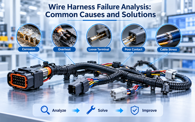
1.Why Wire Harness Failure Analysis Matters
Wire harness failures can affect equipment performance, production continuity, product safety, and maintenance costs.
In industrial automation, an intermittent connection may cause unexpected machine shutdowns. In automotive applications, damaged wiring can interrupt sensor signals or power distribution. In energy storage systems, a poor high-current connection may generate excessive heat and create a serious reliability concern.
Failure analysis helps manufacturers and engineering teams:
- Identify the actual cause instead of treating only the visible symptom.
- Reduce recurring defects and warranty claims.
- Improve wire, terminal, connector, and protective material selection.
- Optimize harness routing and mechanical protection.
- Strengthen manufacturing and inspection processes.
- Improve reliability under real operating conditions.
A structured investigation is particularly important when a failure occurs intermittently or only under specific conditions, such as vibration, temperature changes, moisture exposure, or repeated movement.
2.Common Wire Harness Failure Modes
Wire harness failures generally fall into several categories. Understanding the relationship between the failure symptom and its possible causes helps engineers select the appropriate inspection and testing methods.
2.1 Open Circuit and Intermittent Connection
An open circuit occurs when electrical continuity is interrupted. The connection may be permanently broken or may become intermittent when the harness moves, vibrates, or experiences temperature changes.
Common causes:
- Broken conductors caused by repeated bending or excessive tensile force.
- Poor crimping or incomplete terminal connections.
- Terminal back-out from the connector housing.
- Damaged solder joints or connection interfaces.
- Inadequate strain relief near connectors.
- Incorrect wire routing that places stress on termination points.
Typical symptoms:
- Equipment fails to start or operates intermittently.
- Sensors or control signals disappear unexpectedly.
- Continuity test results change when the harness is moved.
- Electrical faults occur only during vibration or mechanical movement.
Recommended solutions:
- Inspect conductor continuity and terminal retention.
- Examine crimped connections for conductor damage and incomplete compression.
- Check connector locking features and terminal insertion depth.
- Improve strain relief and provide sufficient service loops where appropriate.
- Review routing to prevent tension at connector interfaces.
- Conduct continuity testing while applying controlled mechanical movement when investigating intermittent faults.
A stable connection depends on both electrical contact quality and proper mechanical support. Simply replacing the damaged terminal may not solve the problem if the original routing or strain condition remains unchanged.
2.2 High Contact Resistance and Overheating
High resistance at a connection can cause excessive voltage drop and localized heat generation. This issue is particularly important in power distribution and high-current wire harness applications.
Common causes:
- Insufficient or inconsistent crimp compression.
- Incorrect terminal and conductor size matching.
- Contaminated or oxidized contact surfaces.
- Loose terminal connections.
- Damaged contact plating.
- Inadequate contact force or improper connector mating.
Typical symptoms:
- Abnormal temperature rise near a terminal or connector.
- Discoloration or deformation of connector components.
- Increased voltage drop under load.
- Unstable electrical performance.
- Burnt insulation or localized thermal damage in severe cases.
Recommended solutions:
- Verify conductor cross-section and terminal compatibility.
- Inspect crimp geometry and applicable crimp process parameters.
- Measure contact resistance using an appropriate test method.
- Check connector mating condition and terminal contact surfaces.
- Evaluate current rating under actual operating and thermal conditions.
- Review terminal material, plating, and connector selection.
For high-current applications, engineers should assess the complete electrical path rather than evaluating the wire alone. Terminal design, connector interfaces, conductor size, ambient temperature, and heat dissipation all influence the final performance.
2.3 Insulation Damage and Electrical Short Circuits
Insulation protects conductors from unintended electrical contact, moisture, chemicals, and mechanical damage. When insulation is compromised, the harness may develop leakage current, short circuits, or reduced electrical insulation performance.
Common causes:
- Excessive stripping length or incorrect stripping settings.
- Sharp edges on metal brackets or equipment enclosures.
- Abrasion between wires or against surrounding structures.
- Excessive bending or crushing during installation.
- Incompatible insulation materials and environmental conditions.
- Heat exposure beyond the selected material’s capability.
Typical symptoms:
- Visible cuts, cracks, or exposed conductors.
- Insulation resistance deterioration.
- Short circuits between adjacent conductors or grounded structures.
- Intermittent faults when the harness is flexed.
- Localized melting or deformation.
Recommended solutions:
- Inspect insulation condition at stripping, crimping, and assembly stages.
- Apply suitable protective sleeves, conduits, grommets, or edge protection.
- Maintain appropriate clearance from sharp edges and moving components.
- Select insulation materials based on temperature, chemical, and mechanical requirements.
- Define suitable bend radius and installation constraints.
- Perform insulation resistance or dielectric testing according to the product specification and applicable safety requirements.
Insulation damage should be investigated beyond the visible defect. If abrasion is caused by an incorrect routing path, replacing the damaged section without changing the installation design may only delay another failure.
2.4 Conductor Fatigue and Wire Breakage
Conductor fatigue is a common failure mechanism in applications involving repeated movement, vibration, or bending.
Repeated mechanical stress can gradually damage individual strands. As the number of damaged strands increases, the remaining conductor may experience higher stress and eventually break.
Common causes:
- Repeated bending beyond the wire’s suitable dynamic capability.
- Insufficient bend radius.
- Excessive vibration near fixed connection points.
- Incorrect cable selection for continuous-flex applications.
- Poor strain relief.
- Repeated twisting or pulling during installation and operation.
Typical symptoms:
- Broken copper strands.
- Intermittent electrical continuity.
- Visible cracking or deformation near the termination.
- Electrical faults that appear after repeated movement.
- Reduced mechanical flexibility.
Recommended solutions:
- Select wire constructions suitable for the actual movement profile.
- Evaluate conductor stranding, insulation flexibility, and cable construction.
- Maintain the manufacturer’s recommended minimum bend radius.
- Reduce stress concentration at connector exits.
- Use suitable clamps and strain-relief structures.
- Validate dynamic applications through representative flexing, torsion, or vibration testing.
For robotic systems, drag-chain applications, and moving machinery, static wire specifications are not sufficient. Engineers should consider bending direction, travel distance, acceleration, cycle frequency, and expected service life.
2.5 Terminal Pull-Out and Connector Assembly Failure
A terminal may move backward, become loose, or separate from the connector housing. This can interrupt electrical contact even when the conductor and crimp connection remain intact.
Common causes:
- Incomplete terminal insertion.
- Incorrect terminal orientation.
- Damaged primary locking features.
- Incompatible terminal and housing combinations.
- Improper assembly tools or procedures.
- Excessive cable tension during installation.
- Missing or incorrectly installed secondary locking devices where required.
Typical symptoms:
- Terminal position differs from adjacent terminals.
- Connector fails retention or mating checks.
- Electrical contact becomes unstable after mating.
- Visible terminal movement when the wire is pulled lightly.
- Connector locking features show damage.
Recommended solutions:
- Verify terminal and housing compatibility.
- Check insertion depth and terminal orientation.
- Inspect primary and secondary locking mechanisms.
- Use appropriate assembly fixtures and insertion tools.
- Establish terminal retention inspection requirements.
- Ensure connector assembly instructions clearly define installation and verification steps.
Connector assembly quality should be evaluated as part of the complete harness system. A correctly crimped terminal can still fail if it is not properly retained inside the connector housing.
2.6 Corrosion and Environmental Degradation
Wire harnesses used in outdoor, automotive, marine, medical, and industrial environments may be exposed to moisture, condensation, salt, chemicals, dust, or temperature cycling.
Environmental exposure can degrade insulation, corrode conductive surfaces, and weaken electrical connections.
Common causes:
- Inadequate sealing at connector interfaces.
- Incorrect material selection for the operating environment.
- Damaged seals or improperly installed gaskets.
- Moisture entering through cable entries or connector backshells.
- Exposure to corrosive chemicals or salt-containing environments.
- Poor storage and handling conditions.
Typical symptoms:
- Corrosion on terminals or contacts.
- Greenish or dark deposits on copper conductors.
- Increased contact resistance.
- Insulation swelling, cracking, or discoloration.
- Moisture inside connector housings.
Recommended solutions:
- Select connectors with suitable ingress protection for the actual application.
- Verify seal compatibility with cable diameter and installation conditions.
- Inspect gaskets, cable entries, and connector mating interfaces.
- Select suitable conductor and contact materials or protective plating.
- Conduct relevant environmental validation, such as humidity, temperature cycling, or salt spray testing where applicable.
- Review installation practices to prevent seal damage.
An IP rating describes protection under specified test conditions. It should not be treated as a guarantee of performance under every real-world exposure scenario. Connector selection and validation must reflect the complete application environment.
3.Root Causes Across the Wire Harness Manufacturing Process
Some failures are not caused by a single component defect. They originate from process variations or insufficient coordination between design, material selection, and manufacturing.
The following table connects common manufacturing stages with potential failure risks.
| Manufacturing stage | Potential failure risk | Recommended control |
|---|---|---|
| Wire cutting and stripping | Conductor nicking, insulation damage, incorrect stripping length | Tool setup verification and first-piece inspection |
| Terminal crimping | Loose connection, strand damage, inconsistent crimp geometry | Crimp parameter monitoring and applicable crimp inspection |
| Terminal insertion | Incomplete insertion, terminal back-out | Insertion verification and retention checks |
| Connector assembly | Incorrect configuration, damaged locking features | Assembly instructions and visual verification |
| Harness routing and bundling | Excessive tension, sharp bends, abrasion | Routing review and dimensional inspection |
| Protective covering | Incomplete coverage, incorrect material or installation | Material verification and coverage inspection |
| Final electrical testing | Open circuits, shorts, incorrect pin assignments | Defined continuity and insulation test procedures |
A robust manufacturing system should connect each potential failure mode to a preventive control and a verification method. This makes it easier to identify where a defect entered the process and whether existing controls are effective.
4.A Structured Approach to Wire Harness Failure Analysis
When a wire harness fails, an effective investigation should follow a consistent process. Randomly replacing components can increase repair time without identifying the underlying issue.
Step 1: Define the Failure Symptoms
Start by documenting exactly what happened.
Important information includes:
- What function stopped working?
- Was the failure permanent or intermittent?
- Did it occur during installation, startup, normal operation, or maintenance?
- Was the harness exposed to vibration, moisture, heat, or mechanical movement?
- Did the fault appear immediately or after a period of service?
Record the operating conditions and available equipment error codes before disassembling the harness.
Step 2: Preserve and Inspect the Failed Assembly
Whenever possible, retain the failed harness in its original condition.
Photograph the affected area and record connector positions, routing, mounting points, and visible damage. Avoid cutting or removing components before documenting the evidence.
Visual inspection should focus on:
- Insulation damage and conductor exposure.
- Terminal deformation or corrosion.
- Connector housing cracks and locking damage.
- Abnormal bending or crushing.
- Signs of overheating or discoloration.
- Incorrect assembly or missing protective components.
Preserving the original condition helps engineers understand how the failure developed.
Step 3: Perform Electrical and Mechanical Tests
Choose tests based on the suspected failure mechanism.
| Test method | Primary purpose |
|---|---|
| Continuity testing | Identify open circuits and incorrect connections |
| Insulation resistance testing | Evaluate insulation condition between specified conductors or circuits |
| Dielectric withstand testing | Verify insulation withstand capability under defined test conditions |
| Contact resistance measurement | Assess electrical connection resistance |
| Voltage drop testing | Evaluate losses across a connection under defined load conditions |
| Terminal retention testing | Evaluate mechanical retention within the connector |
| Crimp pull testing | Assess the mechanical strength of a crimped connection |
| Flexing or vibration testing | Investigate failures related to repeated movement or vibration |
| Thermal inspection | Identify abnormal temperature rise during operation |
Not every test is appropriate for every harness. Test voltage, current, duration, acceptance limits, and test sequence must be defined according to the product design, customer requirements, and applicable standards.
Step 4: Identify the Root Cause
A useful investigation separates the observed symptom from the actual cause.
For example:
- Symptom: Intermittent signal loss.
- Finding: Continuity changes when the cable is bent near the connector.
- Root cause: Conductor fatigue caused by repeated bending at an unsupported termination.
- Corrective action: Revise the cable routing and add suitable strain relief, then validate the updated design under representative movement conditions.
Methods such as the 5 Whys and fishbone diagrams can help teams examine potential causes across people, materials, machines, methods, measurements, and environmental conditions.
Engineers should avoid stopping at explanations such as “operator error” or “poor quality.” The investigation should identify the specific process or design condition that allowed the failure to occur.
Step 5: Implement and Verify Corrective Actions
Corrective actions should address the confirmed root cause rather than simply replacing the failed part.
After implementing a change:
- Update the relevant drawing, BOM, work instruction, or process parameter.
- Define the required validation tests.
- Inspect representative samples or production lots.
- Confirm that the original failure mode has been eliminated under relevant conditions.
- Monitor subsequent production or field performance.
- Document the investigation and corrective action results.
A corrective action is not complete until its effectiveness has been verified.
5.Preventing Wire Harness Failures Through Better Design
The most cost-effective failure analysis is often the one that never needs to happen. Many common failure modes can be reduced through appropriate design decisions before production begins.
5.1 Select Wires and Materials Based on Application Conditions
Wire selection should consider more than conductor size and rated voltage.
Relevant factors include:
- Current-carrying requirements.
- Operating and ambient temperature.
- Static or dynamic bending conditions.
- Chemical and moisture exposure.
- Abrasion and vibration.
- Insulation material properties.
- Installation space and routing limitations.
For example, a harness used in a stationary control cabinet may have very different requirements from one installed on a moving robotic arm.
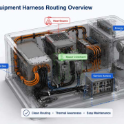
5.2 Optimize Routing and Mechanical Protection
Harness routing directly affects mechanical reliability.
Design reviews should evaluate:
- Minimum bend radius.
- Clearance from sharp edges and heat sources.
- Distance from moving mechanical components.
- Clamping positions and support intervals.
- Connector exit direction.
- Strain relief and serviceability.
- Potential interference during equipment movement.
Protective sleeves, corrugated conduits, braided coverings, grommets, and clamps should be selected according to the specific mechanical and environmental risks.
Adding protection without understanding the failure mechanism may increase harness size and assembly complexity without solving the underlying problem.
5.3 Improve Connector and Terminal Compatibility
Connector and terminal selection should be treated as a system-level engineering decision.
Engineers should verify:
- Wire cross-section compatibility.
- Terminal material and plating requirements.
- Crimp tooling compatibility.
- Housing and terminal part numbers.
- Locking and retention design.
- Current and voltage requirements.
- Environmental sealing performance.
Using individually suitable components does not automatically guarantee a reliable assembled connection. Their compatibility must be verified as a complete system.
5.4 Validate the Design Before Mass Production
Prototype validation helps identify design weaknesses before they become recurring production or field issues.
Depending on the application, validation may include:
- Continuity and insulation testing.
- Crimp quality and terminal retention evaluation.
- Temperature rise testing.
- Vibration and mechanical shock testing.
- Flexing and torsion testing.
- Temperature cycling and humidity exposure.
- Ingress protection testing for relevant sealed assemblies.
The validation plan should be based on the actual operating environment and customer specifications. Testing should reproduce meaningful service conditions rather than simply checking whether a prototype passes a basic electrical test.
6.Building a Continuous Improvement System
Failure analysis becomes more valuable when investigation results are fed back into design and manufacturing.
A practical continuous improvement system should connect field issues, inspection findings, engineering changes, and production records.
6.1 Maintain Traceability
Traceability helps teams identify which materials, production batches, equipment settings, and inspection records are associated with a failed assembly.
Useful records may include:
- Wire and terminal lot information.
- Connector and component batch numbers.
- Production dates and work orders.
- Crimping equipment and tooling records.
- Inspection and electrical test results.
- Engineering drawing and BOM revisions.
- Nonconformance and corrective action reports.
Digital production records can make investigations more efficient by narrowing down the affected materials and manufacturing stages.
6.2 Use Failure Data to Improve Process Controls
Recurring failures should be reviewed to identify patterns.
For example, if terminal back-out repeatedly occurs on the same connector family, the investigation may reveal an insertion fixture issue, an unclear assembly instruction, or a component compatibility problem.
If insulation damage frequently appears at a particular mounting point, the routing design or protective structure may require revision.
Manufacturers can use these findings to update inspection checkpoints, process instructions, tooling maintenance plans, and design guidelines.
6.3 Standardize Corrective and Preventive Actions
A documented corrective action process should include:
- Failure description and evidence.
- Root cause analysis.
- Immediate containment measures.
- Permanent corrective actions.
- Responsible personnel and completion dates.
- Validation results.
- Effectiveness monitoring.
This approach helps ensure that lessons learned from one project can improve similar harness designs and production processes.
How FPIC Approaches Wire Harness Reliability
For custom wire harness projects, reliability depends on coordination between engineering requirements, component selection, manufacturing processes, and final inspection.
With 23 years of experience in connector and cable assembly manufacturing, FPIC supports customized wire harness development for industrial, automotive, medical, and new energy applications.
A structured project approach helps address potential failure risks at different stages:
- Engineering review: Evaluate electrical requirements, connector configurations, routing, and application conditions.
- Component selection: Match wires, terminals, connectors, and protective materials to the intended operating environment.
- Manufacturing control: Apply defined procedures for cutting, stripping, crimping, terminal insertion, and harness assembly.
- Quality verification: Use appropriate visual, dimensional, mechanical, and electrical inspection methods according to project requirements.
- Engineering feedback: Review identified issues and coordinate design or process improvements when necessary.
For customized assemblies, early communication about operating temperature, current load, movement, vibration, installation space, and environmental exposure can help reduce design risks before mass production.
Conclusion
Wire harness failures can originate from electrical connection problems, insulation damage, conductor fatigue, terminal retention issues, corrosion, or manufacturing process variations.
The most effective way to improve reliability is to investigate the complete failure mechanism rather than focusing only on the damaged component.
By combining structured root cause analysis, suitable material selection, optimized routing, controlled manufacturing processes, and application-based validation, manufacturers can reduce recurring failures and improve long-term harness performance.
A reliable wire harness is not simply an assembly that passes an electrical test at the end of production. It is a product designed, manufactured, and verified to perform consistently under its intended operating conditions.
FAQ
What are the most common causes of wire harness failure?
Common causes include broken conductors, poor crimp connections, high contact resistance, insulation damage, terminal back-out, corrosion, and excessive mechanical stress. Environmental conditions and manufacturing process variations can also contribute to failures.
How can I identify an intermittent wire harness failure?
Begin with a visual inspection and continuity testing. If the fault occurs during movement or vibration, perform controlled flexing or movement tests while monitoring electrical continuity. Also inspect terminal retention, connector locking features, and strain relief.
What tests are used for wire harness failure analysis?
Common methods include continuity testing, insulation resistance testing, dielectric withstand testing, contact resistance measurement, voltage drop testing, crimp pull testing, terminal retention testing, and environmental or mechanical validation.
The appropriate test method and acceptance criteria depend on the harness design and application requirements.
Why does a wire harness overheat at the connector?
Overheating may result from high contact resistance, insufficient crimp compression, incorrect terminal selection, loose connections, excessive current, or inadequate thermal management. The investigation should evaluate both the connection interface and the operating load.
How can wire harness failures be prevented during design?
Prevention starts with selecting suitable wires and connectors, optimizing routing and bend radius, providing adequate strain relief, considering environmental exposure, and validating the design under representative operating conditions.
Can a wire harness pass continuity testing and still fail in operation?
Yes. A harness may pass a static continuity test but fail under vibration, repeated bending, temperature changes, moisture exposure, or electrical load. Additional mechanical, environmental, and application-specific validation may be necessary.
Need Support for a Custom Wire Harness Project?
Selecting the right wire, terminal, connector, and protective structure is essential for long-term reliability.
FPIC supports customized wire harness development and manufacturing for industrial, automotive, medical, and new energy applications.
Contact our engineering team to discuss your application requirements, technical drawings, and customized wire harness solutions.
Resources
- IPC/WHMA-A-620 – Requirements and Acceptance for Cable and Wire Harness Assemblies
Industry reference for workmanship and acceptance requirements in cable and wire harness assemblies. - NASA Workmanship Standards
Technical workmanship resources covering electrical and electronic assembly practices. - SAE International
Standards and engineering resources relevant to automotive electrical systems and component reliability. - UL Solutions
Product safety, testing, and certification resources for electrical components and assemblies.