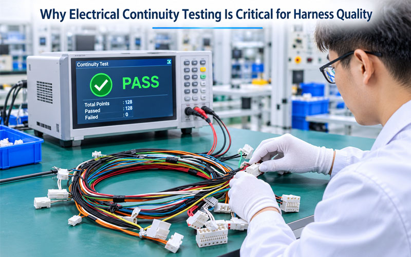
Why Electrical Continuity Testing Is Critical for Harness Quality
A wire harness may look correct after assembly, with properly installed terminals, secure connectors, and neatly arranged branches. However, visual inspection alone cannot confirm that every circuit has the correct electrical connection.
A single disconnected conductor, incorrectly inserted terminal, crossed wire, or unintended short circuit can prevent an entire electrical system from operating properly. In automotive, industrial automation, medical equipment, and energy storage applications, these defects can lead to equipment malfunction, production downtime, or costly field failures.
Electrical continuity testing is therefore an essential quality-control step in wire harness manufacturing. It verifies that the intended electrical paths exist and helps identify wiring errors before a finished assembly is released.
This article explains how continuity testing works, which defects it can detect, how manufacturers can improve testing reliability, and why it should be integrated into a broader wire harness quality-control process.
1.What Is Electrical Continuity Testing?
Electrical continuity testing is a method used to verify that an electrical path is complete between designated connection points.
In a wire harness, each conductor is designed to connect specific terminals or connector cavities. A continuity tester applies a controlled electrical signal through the circuit and determines whether the measured path meets the defined acceptance criteria.
For a typical point-to-point harness, the test system compares the actual electrical connections with the approved wiring diagram, pin assignment table, or test program.
A properly configured system can identify:
- Open circuits caused by broken or disconnected conductors
- Incorrect wire-to-pin connections
- Crossed or swapped conductors
- Unintended connections between separate circuits
- Missing or incorrectly installed terminals
- Certain abnormal resistance conditions when resistance measurement is included in the test specification
Modern automated harness testers can check multiple circuits in one test sequence, making them suitable for both complex assemblies and repetitive mass-production operations.
It is important to distinguish a basic continuity check from a more detailed electrical resistance measurement. A simple pass/fail continuity result confirms that a conductive path exists below a specified threshold. It does not automatically prove that the conductor or contact resistance is within every application-specific requirement.
2.Why Continuity Testing Is Critical for Wire Harness Quality
2.1 Detecting Open Circuits Before Shipment
An open circuit occurs when the intended electrical path is interrupted.
Possible causes include:
- A broken conductor
- An incomplete crimp connection
- A terminal that has not been fully inserted
- A disconnected wire at a splice
- A damaged connection during assembly
- A conductor that has been cut or damaged during processing
An open circuit can prevent a sensor signal, power supply, or control command from reaching its destination.
For example, an industrial equipment harness may contain multiple power and signal circuits. If one signal conductor is disconnected, the equipment controller may fail to receive feedback from the corresponding sensor.
Continuity testing helps identify these interruptions before the harness reaches the customer’s equipment.
2.2 Identifying Short Circuits and Unintended Connections
A short circuit occurs when two circuits that should remain electrically isolated become unintentionally connected.
This can result from:
- Damaged wire insulation
- Incorrect terminal placement
- Exposed conductor strands
- Conductive debris
- Improper routing or assembly
- Incorrect connections inside a splice or connector
A low-voltage shorts test can identify unintended electrical connections between circuits, provided that the test program includes the relevant isolation checks.
This is particularly important for harnesses containing multiple power, ground, and signal circuits. An unintended connection may cause incorrect signals, abnormal current paths, or equipment malfunction.
2.3 Verifying Correct Pin-to-Pin Connections
Correct electrical continuity does not always mean correct wiring.
For example, two wires may both have complete electrical paths but terminate at the wrong connector cavities. This is a miswiring or pin-assignment error.
A simple buzzer-based continuity check may not identify every crossed connection. A programmed harness tester can compare the measured connections against a defined netlist or pin-to-pin table.
This allows the manufacturer to verify that:
- Each wire reaches its intended terminal
- Connector cavity assignments match the approved drawing
- No two circuits have been unintentionally swapped
- All specified electrical connections are present
For complex wire harness assemblies, pin-to-pin verification is just as important as detecting open circuits.
2.4 Reducing Rework and Field Failure Risks
Finding an electrical defect during production is generally easier and less expensive than identifying it after installation.
Without effective testing, defective harnesses may proceed to final packaging, shipment, or equipment integration. If a problem is discovered at the customer’s assembly line, the consequences may include additional inspection, replacement, production delays, and transportation costs.
A structured continuity testing process provides an additional opportunity to detect wiring defects before delivery.
It also generates useful quality data that manufacturers can analyze to identify recurring problems in wire processing, crimping, terminal insertion, and assembly operations.
3.Common Wire Harness Defects Detected by Continuity Testing
Different electrical defects produce different test results. Understanding these differences helps manufacturers establish suitable test programs and failure-analysis procedures.
| Defect Type | Typical Cause | Expected Test Indication |
|---|---|---|
| Open circuit | Broken wire or incomplete connection | No valid path |
| Short circuit | Damaged insulation or unintended contact | Connection detected between isolated circuits |
| Miswiring | Incorrect wire-to-cavity assignment | Actual connection differs from the approved pin map |
| Missing terminal | Terminal omitted during assembly | Expected connection is absent |
| Crossed wires | Two or more wires connected to incorrect cavities | Incorrect connection pattern |
| Abnormal resistance | Poor contact, damaged conductor, or connection issue | Resistance exceeds the specified limit, if measured |
Not every defect can be detected by a basic continuity test. For example, damaged insulation that has not yet created a short circuit may pass a continuity check. Similarly, a mechanically weak crimp may still conduct electricity during a low-current test.
This is why continuity testing should be combined with appropriate visual, dimensional, mechanical, and other electrical inspections.
4.How Does a Wire Harness Continuity Test Work?
A typical continuity testing process involves several steps.
Step 1: Define the Electrical Test Requirements
Before testing begins, the manufacturer needs an approved electrical reference.
This may include:
- Wiring diagrams
- Connector pin assignment tables
- Circuit netlists
- Bill of materials and product configuration
- Required resistance limits
- Short-circuit detection requirements
- Customer-specific test instructions
The test program should reflect the latest approved engineering revision. If a connector pin assignment changes during an engineering change, the corresponding test program must also be reviewed and updated.
Step 2: Connect the Harness to the Test Fixture
The harness is connected to a dedicated test fixture, adapter cable, or interface that matches its connector configuration.
The fixture establishes electrical contact with the designated terminals or connector cavities.
Fixture design is important because poor contact, damaged test pins, incorrect adapters, or unstable connections can produce misleading results.
For assemblies with delicate or specialized connectors, suitable mating adapters should be used to avoid damaging the product interface.
Step 3: Apply a Controlled Test Signal
The tester applies a controlled electrical signal through the selected circuits.
For basic continuity testing, the equipment checks whether the measured path falls within the programmed acceptance threshold.
The test voltage and current must be suitable for the assembly. They should be defined according to the product design, connected components, and customer requirements rather than selected from a universal value.
This is particularly important for harnesses containing electronic components, sensors, protective devices, or other circuits that may be sensitive to test conditions.
Step 4: Compare Actual Connections with the Test Program
The test system compares measured connections with the approved wiring configuration.
Depending on the equipment and program, it may check:
- Expected circuit connections
- Missing connections
- Unintended connections
- Incorrect pin assignments
- Resistance values against defined limits
For complex harnesses, automated testing can reduce the possibility of overlooking individual circuits during manual inspection.
Step 5: Record Results and Handle Failures
After testing, the harness receives a pass or fail result according to the defined acceptance criteria.
Failed assemblies should be identified and separated from conforming products. The manufacturer should investigate the suspected circuit, inspect the relevant connection, and determine the root cause.
After an approved repair or rework, the affected assembly should be retested according to the applicable procedure before release.
5.Manual vs. Automated Continuity Testing
Both manual and automated testing methods are used in wire harness manufacturing. The appropriate choice depends on circuit quantity, assembly complexity, production volume, and required test coverage.
| Comparison | Manual Testing | Automated Harness Testing |
|---|---|---|
| Operation | Operator uses probes or a basic meter | Tester follows a programmed sequence |
| Circuit coverage | Often limited to selected points | Can cover multiple or all specified circuits |
| Pin-to-pin verification | Depends on operator procedure | Can compare against a programmed netlist |
| Testing efficiency | More time-consuming for complex harnesses | Generally faster for repetitive testing |
| Result recording | May require manual documentation | Can support electronic result records |
| Best suited for | Simple checks and troubleshooting | Complex assemblies and production testing |
Manual Testing
A digital multimeter can be used to check whether a specific conductor has a conductive path.
Manual testing is useful for troubleshooting, prototype verification, and investigating individual circuits. However, checking a complex harness point by point can be time-consuming and increases dependence on operator attention and documentation.
Automated Testing
Automated cable and harness testers use dedicated interfaces and programmed test sequences to verify circuit connections.
Depending on the system, they can detect open circuits, shorts, and incorrect wiring patterns across multiple terminals.
For production environments, automated testing offers more repeatable test execution and can support electronic result recording. However, automation does not eliminate the need for correct fixture design, program validation, and regular equipment verification.
6.Continuity Testing vs. Insulation Resistance and Hi-Pot Testing
One of the most important points in wire harness quality management is understanding that different electrical tests verify different characteristics.
Continuity testing, insulation resistance testing, and dielectric withstand testing are not interchangeable.
| Test Type | Main Purpose | What It Verifies |
|---|---|---|
| Continuity Testing | Confirm intended electrical paths | Open circuits and specified connection patterns |
| Shorts Testing | Detect unintended connections | Isolation between circuits that should remain separate |
| Insulation Resistance Testing | Evaluate insulation performance | Resistance to leakage current under specified DC test conditions |
| Hi-Pot / Dielectric Withstand Testing | Verify insulation withstand capability | Ability to withstand a specified electrical stress without unacceptable leakage or breakdown |
| Contact Resistance Testing | Evaluate electrical resistance at contact interfaces | Resistance across mated contacts or defined contact interfaces |
For example, a harness may pass a continuity test because every conductor has a complete electrical path. However, damaged insulation between two conductors may still create a potential safety or reliability problem.
Similarly, a continuity pass does not necessarily demonstrate that a crimp connection or connector contact has sufficiently low resistance under its specified operating conditions.
Additional electrical tests should therefore be selected according to the application, voltage rating, circuit design, connected components, and customer requirements.
For connector contact resistance measurements, IEC 60512-2-1 provides a defined millivolt-level test method. This is different from a basic harness continuity check. Source: IEC 60512-2-1.
7.Common Factors That Affect Continuity Test Accuracy
A continuity tester is only as reliable as the test setup and procedures supporting it.
7.1 Poor Test Fixture Contact
Worn, contaminated, or misaligned test pins can create unstable connections.
This may result in false failures, intermittent readings, or inconsistent resistance measurements.
Manufacturers should inspect fixture contacts regularly, confirm proper connector engagement, and replace worn components when necessary.
7.2 Incorrect Test Program
An outdated or incorrectly configured test program can cause defects to be overlooked or conforming products to fail.
Common program-related issues include:
- Incorrect pin mapping
- Missing circuit definitions
- Incorrect resistance thresholds
- Incomplete short-circuit coverage
- Failure to reflect the latest engineering revision
Test programs should be reviewed and validated whenever the product design, connector configuration, or wiring specification changes.
7.3 Unstable Connections During Testing
A harness may pass when positioned in one way but fail when its branches or connectors are moved.
This can indicate an intermittent connection caused by a damaged conductor, weak termination, or unstable contact interface.
When the application or risk assessment requires it, additional movement-related or dynamic testing may be needed. A static continuity test alone cannot establish long-term resistance to vibration or repeated flexing.
7.4 Incorrect Resistance Thresholds
A continuity threshold that is too permissive may allow an unacceptable connection to pass. A threshold that is too strict may generate unnecessary failures.
Acceptance limits should consider conductor length, wire size, contact interfaces, fixture resistance, measurement capability, and customer specifications.
A basic continuity threshold should not be treated as a substitute for a defined conductor-resistance or contact-resistance requirement.
7.5 Insufficient Test Coverage
Testing only selected wires or connector pins may leave other circuits unchecked.
For critical assemblies, the test plan should define which circuits must be verified and whether all specified connections and isolation relationships are included.
The required coverage should be agreed upon before production release.
8.Best Practices for Implementing Continuity Testing in Production
A reliable testing process should be built into the manufacturing workflow rather than treated as a final, isolated inspection.
The following practices help improve test consistency.
1.Use approved wiring documentation
Base the test program on the latest released drawings, pin assignment tables, and customer specifications.
2.Validate test programs before production
Confirm that the test fixture and program correctly identify representative open, short, and miswiring conditions where applicable.
3.Define clear acceptance criteria
Document the required circuit coverage, test conditions, resistance limits where applicable, and pass/fail rules.
4.Check test fixtures regularly
Inspect mating interfaces, adapter cables, test pins, and connection stability to reduce fixture-related errors.
5.Integrate testing into the production flow
Perform electrical verification at an appropriate stage after the relevant wiring and connector assembly operations are complete. Additional checks may be needed after processes that could affect electrical connections.
6.Establish a controlled failure-handling process
Identify failed circuits, investigate root causes, document approved rework, and retest affected assemblies before release.
7.Maintain traceable test records
Where required by the customer or quality plan, retain product identification, test results, test-program revision, date, and relevant equipment information.
These records can support defect analysis, process improvement, and customer quality reviews.
9.The Role of Electrical Testing in Overall Wire Harness Quality Control
Continuity testing is an essential part of wire harness quality assurance, but it cannot independently guarantee the quality of a finished assembly.
A comprehensive quality-control process should combine electrical verification with controls at different manufacturing stages.
| Manufacturing Stage | Quality Control Focus |
|---|---|
| Incoming Material Inspection | Wire specifications, terminal dimensions, connector models, and material identification |
| Wire Processing | Cutting length, stripping quality, and conductor strand condition |
| Crimping | Crimp height, terminal position, and mechanical connection quality |
| Connector Assembly | Correct cavity assignment, terminal seating, and locking mechanism engagement |
| Harness Assembly | Routing, branch dimensions, protection materials, and workmanship |
| Electrical Testing | Continuity, shorts, and other specified electrical tests |
| Final Inspection | Appearance, labeling, configuration, and product documentation |
This approach helps manufacturers identify defects at the stage where they occur, rather than relying exclusively on final electrical inspection.
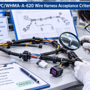
IPC/WHMA-A-620 provides industry requirements and acceptance criteria for cable and wire harness assembly processes, including crimped, mechanically secured, and soldered interconnections. It should be used together with applicable product drawings, customer specifications, and the agreed quality plan. Source: IPC/WHMA-A-620F overview.
10.How FPIC Approaches Wire Harness Electrical Quality
For custom wire harness projects, electrical test requirements should be considered during engineering and manufacturing preparation.
The wiring diagram, connector pin assignments, circuit configuration, and customer-specific requirements provide the basis for defining the appropriate electrical verification process.
With 23 years of experience in connector and cable assembly manufacturing, FPIC understands the importance of connecting engineering requirements with production quality controls.
For different wire harness applications, including automotive, industrial, medical, and new energy equipment, test coverage and acceptance criteria should be adapted to the actual product design and operating conditions.
A well-defined electrical testing process helps verify circuit connections, identify assembly errors, and provide customers with greater confidence in finished harness quality.
Conclusion
Electrical continuity testing is more than a simple pass/fail inspection. It is a practical method for verifying that wire harness circuits are connected according to the approved design.
By detecting open circuits, shorts, and incorrect pin assignments before shipment, manufacturers can reduce avoidable assembly defects and improve production consistency.
However, continuity testing has clear limitations. It does not replace insulation resistance, dielectric withstand, contact resistance, or mechanical validation when those tests are required.
The most reliable approach combines an accurate test program, suitable fixtures, clearly defined acceptance criteria, controlled failure handling, and traceable quality records.
For custom wire harness projects, defining electrical test requirements early helps align product design, manufacturing processes, and final quality expectations.
FAQ
What is the purpose of electrical continuity testing in wire harness manufacturing?
It verifies that designated conductors and terminals have the intended electrical paths. It helps detect open circuits, missing connections, and incorrect wiring patterns before a harness is released.
Can a continuity test detect short circuits?
A basic continuity check alone may not provide complete short-circuit coverage. A properly configured harness test program can include low-voltage shorts testing to identify unintended connections between circuits that should remain isolated.
Does continuity testing detect incorrect pin assignments?
Yes, when the test system compares actual connections against an approved pin-to-pin table or netlist. A simple buzzer check may not identify every crossed or swapped wire.
Is continuity testing the same as insulation resistance testing?
No. Continuity testing checks whether intended conductive paths exist. Insulation resistance testing evaluates the resistance of insulation between conductors or other specified points under defined test conditions.
Does every wire harness require 100% continuity testing?
The required inspection and test coverage should be defined by the product design, customer requirements, applicable standards, and quality plan. For production harnesses, 100% electrical testing is commonly specified when every finished unit must be verified.
Can a harness pass continuity testing but still fail in actual operation?
Yes. A harness may have complete electrical paths but still contain damaged insulation, weak crimps, unstable contacts, or mechanical defects. Additional electrical and mechanical tests may be necessary depending on the application.
What information should be included in a wire harness electrical test specification?
A useful specification should identify the circuits to be tested, connector pin assignments, test methods, test conditions, acceptance limits, required test coverage, equipment or fixture requirements, and record-retention expectations.
Discuss Your Wire Harness Testing Requirements
Looking for a wire harness manufacturer that understands electrical connection requirements and production quality control?
FPIC supports custom wire harness and cable assembly projects for automotive, industrial, medical, and new energy applications.
Share your wiring diagram, connector specifications, or project requirements with our team to discuss a suitable manufacturing and electrical testing approach.
Resources
- IPC/WHMA-A-620F – Requirements and Acceptance for Cable and Wire Harness Assemblies
Industry standard covering manufacturing practices and acceptance criteria for cable and wire harness assemblies. - IEC 60512-2-1 – Electrical Continuity and Contact Resistance Tests
Defines a millivolt-level method for measuring electrical contact resistance in connector interfaces. - NAC Corporation – What Is Wiring Testing?
Explains wiring tests used to identify disconnections, shorts, miswiring, and surplus circuits. - WHMA – Wire Harness Assembly for Operators: Inspection and Testing
Training resource covering continuity and shorts testing alongside other wire harness inspection and verification methods.