Exploring Common Terminal Crimping Standards and Inspection Guidelines
Terminal crimping is a critical process in wire harness manufacturing. However, within the industry, this procedure often encounters challenges leading to subpar results. Elevating the success rate of terminal crimping operations is essential to ensure the quality of wire harness products, significantly enhance production capacity, and improve overall efficiency.
Introduction to Terminal Crimping:
Terminal crimping involves applying pressure in the contact area between a wire and a terminal to shape and create a secure connection.
Requirements for Terminal Crimping:
The key to successful crimping lies in providing an inseparable, long-lasting, reliable electrical and mechanical connection between terminals and wires, while also facilitating efficient production processes.
Objectives of Terminal Crimping:
Terminal crimping aims to meet product requirements such as rated current, voltage, circuit size, joint strength, structure, termination methods, and safety features.
Advantages of Terminal Crimping:
- Tailored Solutions: Specific crimping structures can be calculated to suit a defined range of wire diameters and thicknesses.
- Flexibilität: Die Anpassung der Crimphöhe ermöglicht die Kompatibilität mit verschiedenen Drahtdurchmessern.
- Kosteneffizienz: Die kontinuierliche Stanzproduktion führt zu kosteneffizienten Ergebnissen.
- Automatisierung: Crimpprozesse für Anschlüsse können automatisiert werden, um die Produktionseffizienz zu steigern.
- Stabilität in rauen Umgebungen: Das Crimpen von Anschlüssen zeigt auch unter anspruchsvollen Bedingungen eine konstante Leistung.
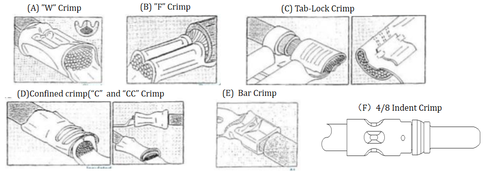
A&E: Crimpen von nicht isolierten Anschlüssen – Werkzeuge: Pneumatische Crimpzangen und manuelle Crimpwerkzeuge. Das Punktcrimpen, bei dem die Anschlussverbindung nicht isoliert bleibt, umfasst verschiedene Arten, wie z. B. nicht isolierte Schnellanschlussklemmen, Ringkabelschuhe, Flachstecker, 187-Klemmen, 250-Klemmen und mehr.
B: Gängige CH- und IH-Crimpwerkzeuge: Crimpmaschine für Kabelschuhe und manuelle Crimpwerkzeuge. Das Stanzcrimpen, bei dem die CH- und IH-Teile des Anschlusses gecrimpt werden, umfasst verschiedene Arten, wie z. B. gängige CH- und IH-Ringkabelschuhe, Flachstecker, 187-Klemmen, 250-Klemmen und Steckergehäuse.
C: Halbgeschlossenes Crimpen – Werkzeuge: Terminal-Crimpmaschine. Punktcrimpung mit einer Lücke zwischen CH und IH, typischerweise verwendet für 187- und 250-Fahnenklemmen.
D: Crimpen von isolierten Anschlüssen – Werkzeuge: Pneumatische Crimpzangen und manuelle Crimpwerkzeuge. Punktcrimpung mit isoliertem Anschlussanschluss, umfasst verschiedene Typen wie isolierte Schnellverbindungsanschlüsse, Ringkabelschuhe, Flachstecker, 187 Anschlüsse, 250 Anschlüsse und mehr.
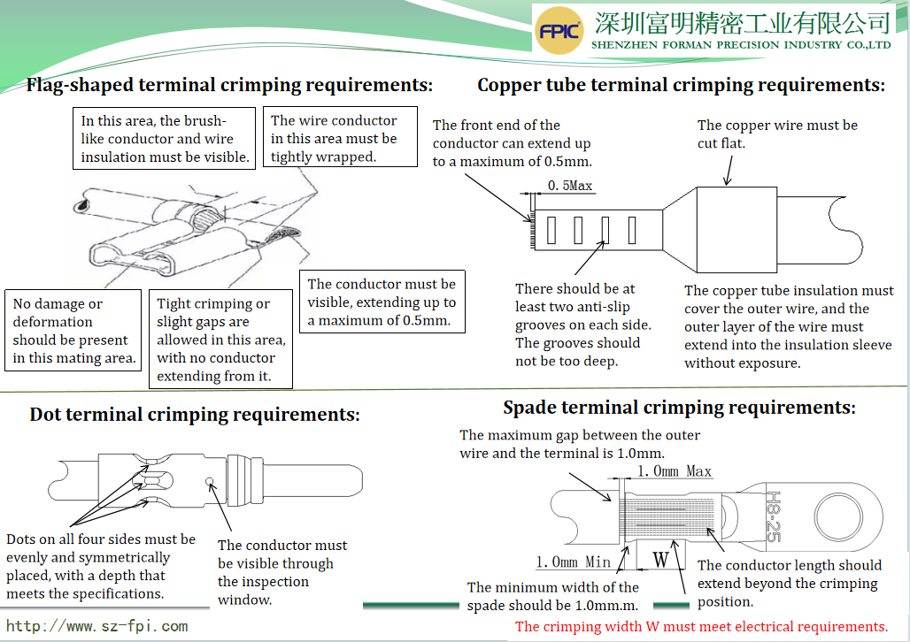
F: Four-Point Crimping – Tools: Four-Point Crimping Machine & Manual Crimping Tools. Point crimping where all sides of the terminal connection are crimped symmetrically, often used in waterproof automotive connectors.
Terminal Crimping Component Names and Crimping Specifications:
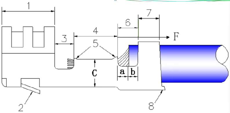
- Terminal Fitting Area – No crimping damage, distortion, or deformation.
- Spring Contact Area (Terminal Locking) – No deformation, normal outward expansion.
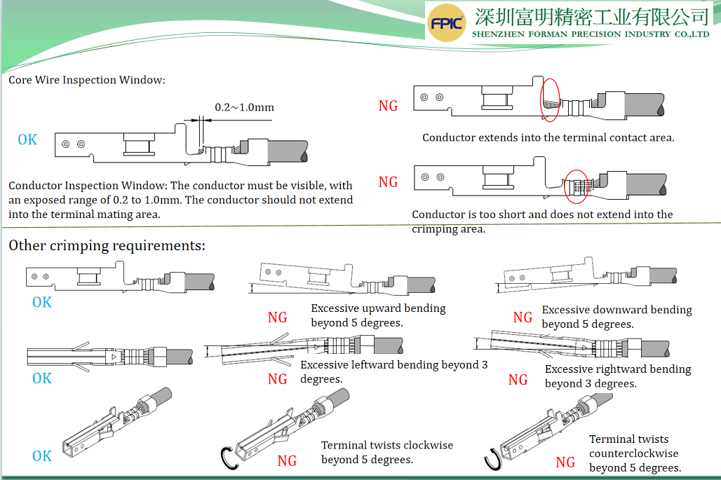
- Core Wire Viewing Window Area – Wire conductor must be visible, conductor exposed between 0.2 to 1.0mm, not extending into the terminal fitting area.
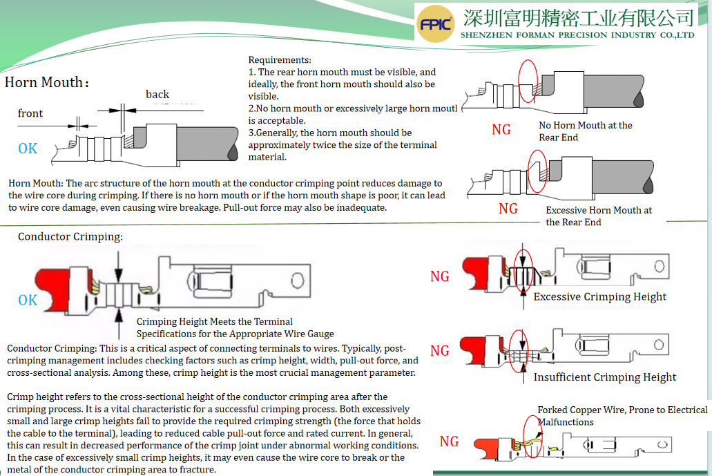
- Core Wire Crimping Area (CH: Crimping Height; CW: Crimping Width) – Must be fully closed, encompassing all conductors, no conductor prongs, and no visible insulation outside.
- Bell Mouth – Front and rear bell mouths must be visible, optimal size range 0.1 to 0.4mm.
- Insulation Skin Observation Area – Conductor and insulation skin must be simultaneously visible.
- Insulation Skin Crimping Area (IH: Insulation Crimping Height; IW: Insulation Crimping Width) – Must be tightly crimped, no wire looseness, terminal curling must not pierce insulation, contacting conductor.
- Terminal Web – The remaining portion of the web connecting the terminal and feed strip should not damage wire insulation or sealing plugs. The maximum length of the terminal web should not exceed 0.5mm.
Common Crimping Appearance Assessment Criteria:
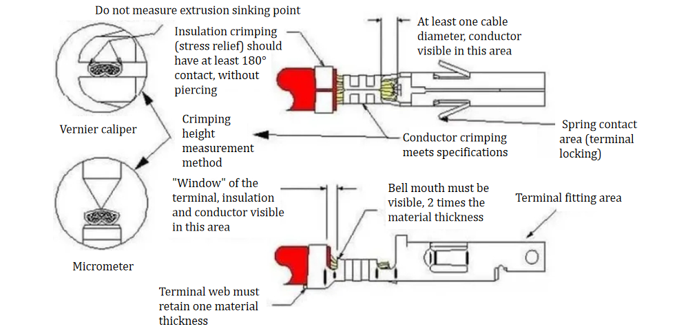
Refer to the image above for correctly executed crimping examples. Insulation crimping compresses the insulation layer but does not pierce it. The wire core (or wire brush) extends a distance at least equal to the diameter of the cable conductor in front of the conductor crimping area. For example, a 1.02mm (18 AWG) cable should extend at least 1.0mm. The portion between the insulation and conductor crimping areas should reveal the insulation layer and conductor. The conductor crimping area features a bell-mouth shape at both ends, and the transition and joint areas remain consistent throughout the crimping process. The terminal plating layer remains undamaged.
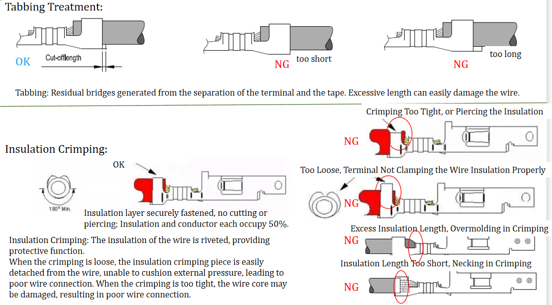
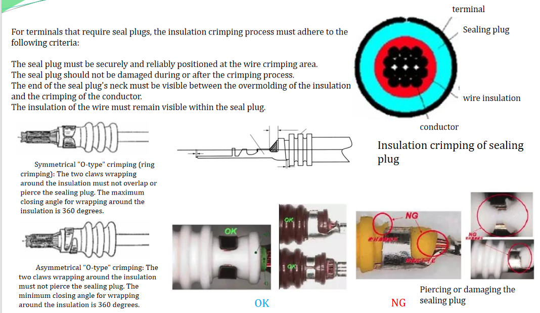
Insulation Crimping Requirements for Terminals with Seal Plugs: