Battery Pack Wire Harness Design for ESS: Routing, Creepage and Serviceability
Battery energy storage systems are becoming more compact, more integrated, and more demanding in both safety and maintenance efficiency. In this environment, the battery pack wire harness is no longer just a group of cables linking modules and controls. It becomes a critical part of the pack’s electrical architecture, assembly workflow, and field service strategy.
A well-designed harness can do more than complete electrical connections. It can improve installation consistency, support insulation performance, reduce maintenance time, and lower long-term failure risk. For OEMs, integrators, and battery system developers, this means harness design should begin early in the project, not after the mechanical layout is already fixed.
This article focuses on three practical priorities in ESS battery pack wire harness design: routing, creepage and clearance, and serviceability.
Why ESS Battery Pack Harness Design Is Different
Compared with a standard industrial cable assembly, a battery pack harness in an energy storage system must work in a more constrained and risk-sensitive environment. It usually needs to coexist with busbars, contactors, fuses, sensing circuits, battery management systems, and enclosure structures inside limited space.
At the same time, the design must account for multiple real-world conditions, including vibration, heat, sharp edges, moisture, assembly tolerance, and field maintenance access. A harness that appears acceptable in an early prototype may still create problems later if it is difficult to install consistently or difficult to inspect safely.
This is why battery pack harness design should be treated as a system engineering task rather than a simple cable selection exercise.
Key design pressures often include:
- high-voltage and low-voltage circuits inside the same pack
- limited routing space near structural and thermal components
- abrasion and strain at transitions and branch points
- electrical spacing requirements around conductive parts
- maintenance access for diagnosis, replacement, or inspection
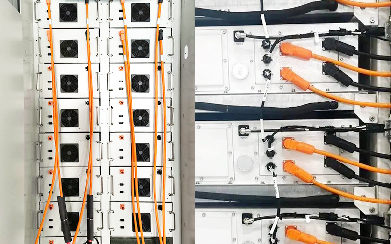
Routing Is More Than Packaging
Routing is often discussed as a space issue, but in an ESS product it is much more than that. Good routing improves electrical safety, assembly repeatability, and service efficiency. Poor routing may lead to insulation wear, unclear harness separation, rework during assembly, and longer maintenance time.
Separate High-Voltage and Low-Voltage Paths Clearly
One of the most important principles in battery pack design is to keep high-voltage and low-voltage circuits logically separated. Power harnesses, interlock loops, signal lines, and sensing branches should not be mixed without clear design intent.
This separation helps in several ways. It supports safer electrical architecture, reduces interference risk, improves visual clarity during assembly, and makes diagnostics more efficient during maintenance. In practical terms, technicians should be able to identify major harness functions quickly rather than tracing an unstructured bundle through the entire pack.
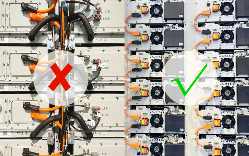
Control Bend Radius and Transition Stress
Harness failures often begin at transition points rather than along protected straight runs. Common risk areas include connector exits, clamp locations, pass-through points, branch breakouts, and areas where the harness changes direction sharply.
These locations require careful control of bend radius, strain relief, retention, and anti-chafe protection. Without that control, the harness may experience insulation damage, terminal stress, conductor fatigue, or sealing problems over time.
A robust design should review:
- minimum bend radius by cable type
- strain relief at connector exits
- clamp spacing and retention logic
- local protection near brackets or metal edges
- movement caused by vibration or thermal cycling
Avoid Heat and Abrasion Risk Zones
The shortest route is not always the right route. A harness may physically fit while still passing too close to hot components, sharp hardware, enclosure ribs, or service access paths.
Routing decisions should always consider real operating conditions. Designers should ask whether the harness could rub during vibration, whether it is exposed to heat concentration, and whether it may be pulled, stepped over, or disturbed during service.
A good routing path protects the harness not only during normal operation, but also during assembly, transport, inspection, and replacement.
Creepage and Clearance Must Be Designed Into the Harness Environment
In high-voltage battery systems, creepage and clearance are basic safety considerations. Clearance is the shortest distance through air between conductive parts. Creepage is the shortest distance along an insulating surface between conductive parts.
In an ESS battery pack, these distances are not controlled only by connector design. They are also influenced by harness routing, support features, enclosure geometry, contamination risk, humidity, and the proximity of conductive hardware.
Support the Pack’s Insulation Strategy
A battery system usually relies on multiple layers of protection, such as insulation materials, spacing, barriers, enclosure design, and isolation monitoring. The harness must support that strategy rather than weaken it.
If a harness is routed too closely to conductive structures, if a branch point is poorly supported, or if contamination and moisture can build surface paths over time, then the intended electrical margins may be compromised in real operation.
That is why harness design should be reviewed together with the broader insulation concept of the battery pack.
Design for Real Assembly and Field Conditions
Electrical spacing should never be judged only by ideal CAD geometry. In production, harnesses shift slightly during installation. Clips may be positioned with tolerance variation. Components move under vibration. Service teams may not always reinstall a branch exactly as it was routed during development.
For this reason, spacing margins should remain reliable under real conditions, including:
- manufacturing tolerance stack-up
- assembly variation
- vibration
- thermal expansion and contraction
- long-term aging
A safe design is one that remains safe after the product enters real use, not only on the original layout drawing.
Pay Extra Attention to High-Risk Interfaces
The most sensitive areas are usually not the center of a protected harness section. They are found at connectors, branch breakouts, pass-through locations, and transitions near busbars, fuses, or contactor assemblies.
These points require special attention because electrical spacing, sealing integrity, mechanical support, and installation repeatability all come together in one area. A strong connector specification alone is not enough if the surrounding harness environment is poorly designed.
Serviceability Should Be Considered From Day One
In many projects, serviceability is reviewed too late. The result is a harness that may work in production but becomes difficult to access, diagnose, or replace in the field.
For energy storage systems, that is a costly mistake. A serviceable design can shorten maintenance time, reduce reconnection errors, and improve overall operational efficiency.
Divide the Harness by Service Logic
Instead of treating the entire pack as one continuous assembly, it is often better to divide the harness into logical sections based on function and service needs.
Typical examples include:
- module signal harness
- sensing harness
- interlock harness
- power sub-harness
- external interface harness
This approach helps isolate faults, simplifies replacement, and avoids unnecessary disassembly when only one section needs attention.
Improve Access and Identification
Clear labeling, consistent connector keying, logical branch identification, and readable routing all improve service performance. In a high-voltage environment, this is not just a convenience issue. It is part of risk reduction.
A serviceable harness should help technicians answer simple but important questions quickly:
- which branch belongs to which function
- which interface is safety-related
- which connector is intended for replacement or inspection
- which route should remain undisturbed during service
Better identification reduces ambiguity, and reduced ambiguity means lower service risk.
Do Not Bury Critical Interfaces
If service disconnects, sensing interfaces, or frequently inspected connectors are buried behind structural layers, maintenance becomes slower and less reliable. This increases the chance that technicians will disturb unrelated parts of the system while trying to reach one specific connection point.
Critical interfaces should be positioned with real maintenance access in mind. A design review should always ask whether a technician can inspect or replace the required section without creating unnecessary disruption elsewhere in the pack.
Validation Points That Should Not Be Ignored
A professional battery pack harness design should be validated through both electrical and mechanical review. Material choice alone is not enough. Layout quality, support quality, and installation consistency must also be verified.
Typical validation items may include:
- continuity testing
- insulation resistance testing
- dielectric withstand or HiPot testing
- terminal or connector retention checks
- vibration testing
- thermal cycling
- sealing validation
- routing verification after installation
These checks help confirm that the harness performs as intended under realistic conditions, not only in a simplified sample state.
How FPIC Supports Custom ESS Harness Development
For ESS and other industrial power applications, harness development is most effective when it begins with system understanding rather than only a parts list. Routing feasibility, connector selection, protection strategy, manufacturing consistency, and validation planning all influence the final result.
FPIC supports custom cable assembly and connector development for industrial and energy-related applications, with experience in design review, sample development, manufacturing process control, and scalable production support. For projects where space is limited and reliability matters, early engineering coordination can reduce development risk and improve overall project efficiency.
Final Thoughts
Battery pack harness design for ESS should never be reduced to conductor size and connector count alone. The harness affects assembly stability, electrical safety, maintenance efficiency, and long-term reliability across the full product lifecycle.
If routing is weak, the pack becomes harder to build and more vulnerable in operation. If creepage and clearance are treated only as connector datasheet values, real safety margins may be reduced. If serviceability is ignored, maintenance becomes slower, less consistent, and more risky.
The strongest designs are the ones that balance electrical performance, packaging efficiency, manufacturability, and service access from the beginning.
FAQ
What makes an ESS battery pack harness different from a standard industrial harness?
An ESS battery pack harness usually has stricter requirements for electrical spacing, routing control, insulation support, and maintenance access. It must often operate in tighter spaces around heat-generating and conductive components.
Why is routing so important in battery pack harness design?
Routing affects more than physical fit. It also influences electrical separation, abrasion risk, thermal exposure, assembly repeatability, and service efficiency.
What is the difference between creepage and clearance?
Clearance is the shortest distance through air between conductive parts. Creepage is the shortest distance along an insulating surface between conductive parts. Both are important in high-voltage battery system design.
Why should serviceability be considered early?
If serviceability is ignored during development, technicians may face difficult access, unclear identification, or unnecessary disassembly during maintenance. Early planning reduces those problems.
What should be checked during validation?
Typical checks include continuity, insulation resistance, dielectric withstand, retention, vibration, thermal cycling, sealing, and routing condition after assembly.
Need Support for a Custom ESS Harness Project?
If you are developing a battery pack, BESS cabinet, or other power-related system, early harness design review can help reduce layout risk, improve manufacturability, and simplify service access. FPIC supports custom wire harness and connector development for industrial and energy applications.
Contact FPIC to discuss your project drawings or technical requirements.
Resources
- Battery Design – Creepage and Clearance: defines creepage as distance along a surface and clearance as distance through air in high-voltage systems.
- Battery Design – Insulation and Isolation: discusses insulation materials, isolation resistance, and the relationship between insulation performance and creepage/clearance in battery pack electrical design.
- Battery Design – Safety Concept: explains how battery pack safety architecture is built around insulation, monitoring, and electrical protection strategies in high-voltage systems.
- Battery Design – High Voltage System: identifies high-voltage connectors, wiring harnesses, busbars, contactors, fuses, and related components as core elements of battery pack electrical design.
- Tesla Powerwall 3 Datasheet: shows a modern ESS product emphasizing modular expansion, harness-based connection, ingress ratings, and relevant UL certifications in an energy storage system context.
